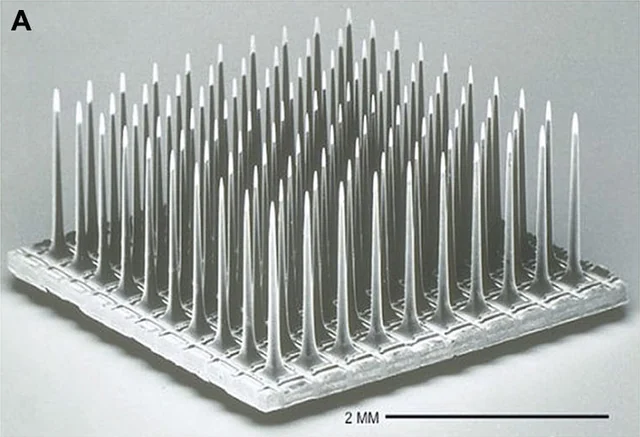
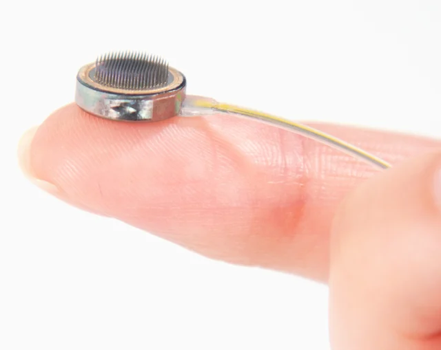
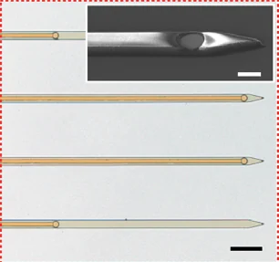
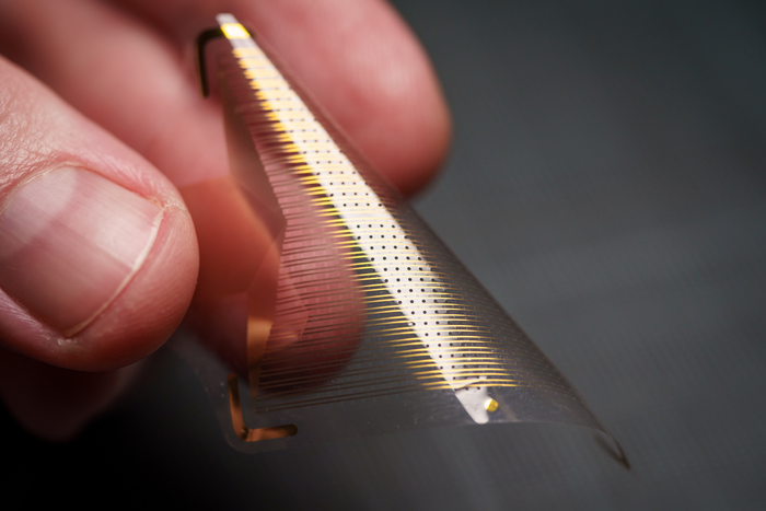
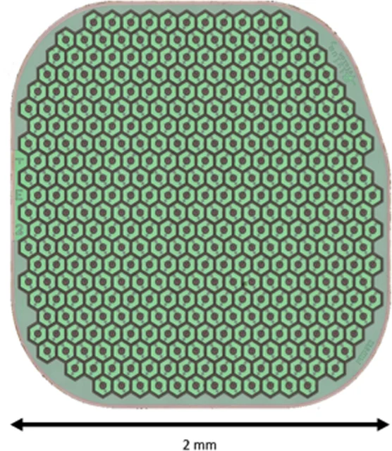
View the interface → Electron micrograph BTSD-0001 Utah electrode array, scanning electron micrograph. 2 mm scale retained.
Utah arrays - Parallel structural variants
Utah Microelectrode Array (UEA) Silicon penetrating arrays with 400 µm electrode pitch. Separates the Utah research family from the 100-electrode, 96-connected NeuroPort configuration and records conflicting manufacturer counts.
The slanted array targets different depths in peripheral nerves. It does not supersede the standard cortical Utah array.
3D model available Intracortical Human evidence
Photo credit Fernandez et al., Frontiers in Neuroengineering (2014), Fig. 1A · Frontiers · Figure 1A · CC BY 3.0 . Photographic panel cropped from the original figure; resized and re-encoded. Original scale bars and annotations retained.
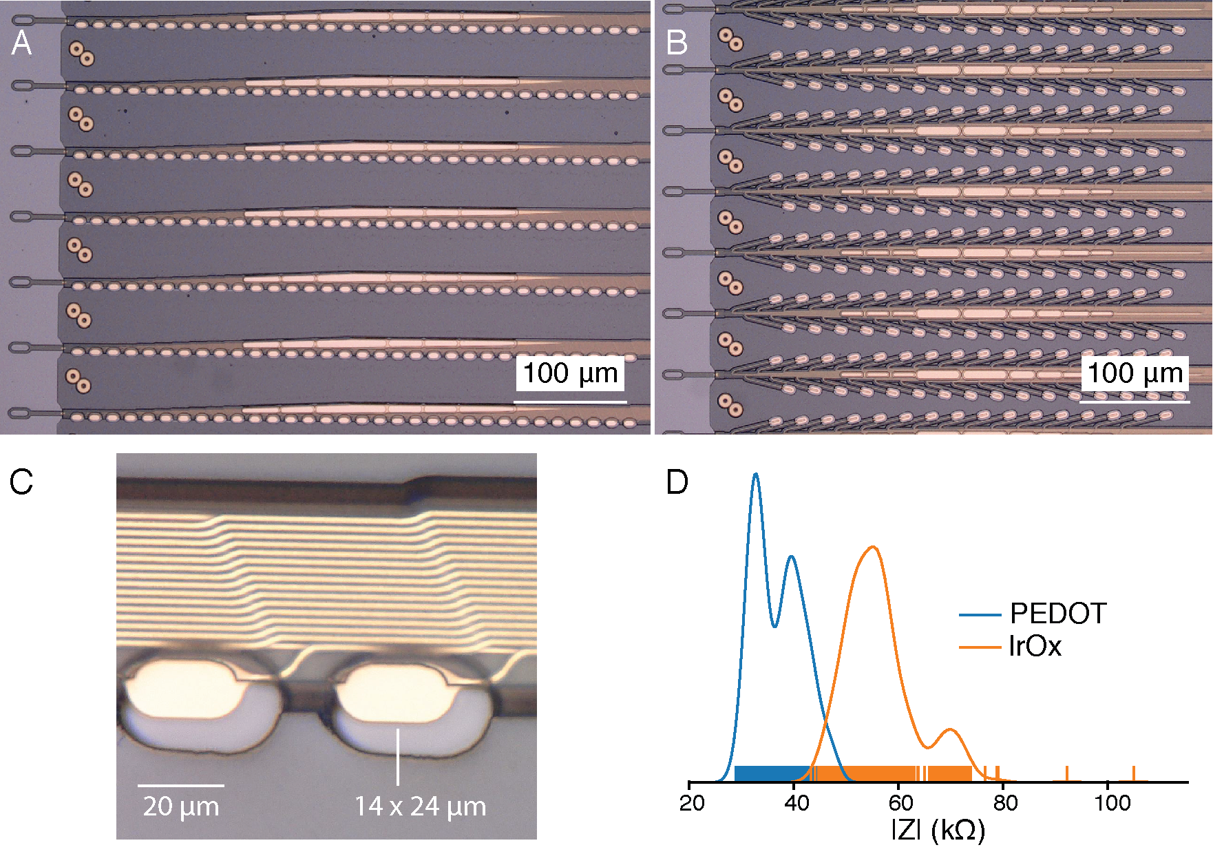
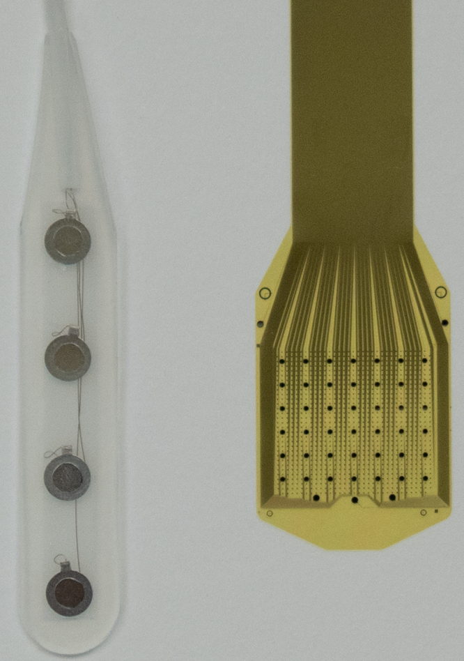
Past versions and parallel branches (1) View the interface → Source figure · 2 views BTSD-0002 Neuralink’s 2019 research thread architecture: two polymer probe designs, electrode contacts and impedance measurements. Historical reference, not the current N1 implant.
Neuralink N1 (flexible-thread implant) Neuralink’s fully implanted, wireless intracortical BCI, with a 3D reference for the documented 2024 N1 configuration: 64 flexible threads and 1,024 sites.
3D model available Intracortical Human evidence
Photo credit Elon Musk and Neuralink, 2019 research white paper, published in JMIR 21(10):e16194 · Neuralink · 2019 research white paper · CC BY-ND 4.0 . Complete figure recovered at its native embedded resolution from the 2019 white paper. Transparency composited on the paper’s white background; no cropping, upscaling, retouching or panel removal. The recovered PNG is copied intact for both display and enlargement.
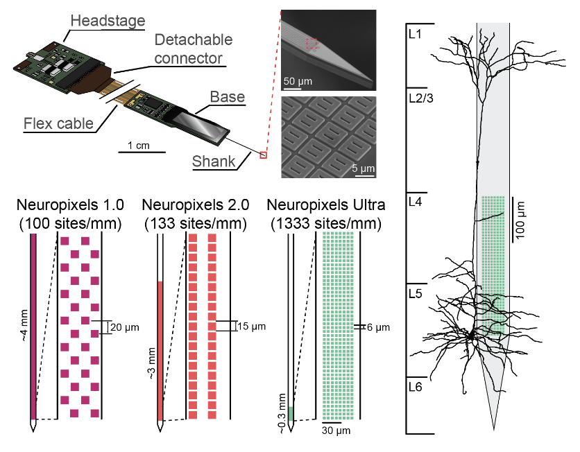
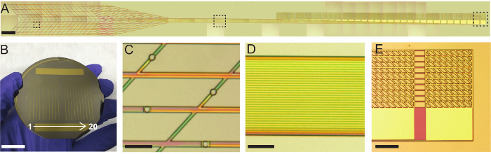
View the interface → Source figure · 3 views BTSD-0004 Neuropixels architecture at a glance: the assembled probe, microscopic contacts, and site layouts for 1.0, 2.0 and Ultra, alongside a cortical neuron.
Pictured: Neuropixels 1.0 recording probe . Other family versions differ.
Neuropixels - Generations and parallel branches
Neuropixels NXT / NP3.0 prototype Official 2026 prototype report: 1,536-channel four-shank NXT, planned NP3.0 name, up to 912 channels mapped to one shank. Access and 2027 sale are forecasts, not completed deliveries.
NXT / NP3.0 is the latest announced generation, still a prototype. Opto, Ultra and NHP solve different problems and remain separate branches.
Intracortical Preclinical evidence
Photo credit Ye and colleagues, Neuropixels Ultra study; architecture overview supplied by the site owner · Neuropixels Ultra · primary study · User-supplied image; source copyright retained . Supplied image copied intact, byte for byte. All labels, panels, scale bars and embedded metadata retained.
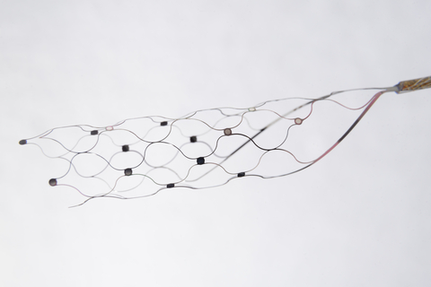
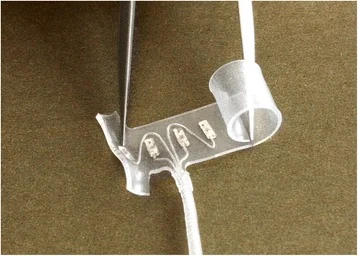
Past versions and parallel branches (6) View the interface → Photograph · 2 views BTSD-0003 Stentrode scaffold and electrode contacts, with the recording lead extending to the right.
Stentrode (Synchron) A fully implanted endovascular BCI: a stent-electrode array in the superior sagittal sinus recording ECoG-like signals, trading spikes for catheter-based deployment.
3D model available Endovascular Human evidence
Photo credit Synchron Stentrode reference image supplied by the site owner; original photographer unspecified · Synchron · device background · User-supplied image; source copyright retained . Supplied image copied intact, byte for byte. All labels, panels, scale bars and embedded metadata retained.
View the interface → Photograph BTSD-IMBCI-0010 Connexus cortical module on a fingertip, showing its penetrating microelectrodes.
Paradromics Connexus (cortical module) Paradromics’ 421-electrode intracortical module, with a source-documented 3D reference model and updated Connect-One early feasibility study context.
3D model available Intracortical Human evidence
Photo credit Paradromics, Inc. — official press kit · Paradromics · official press kit · Official press kit — editorial use with credit . Editorial crop centered on the cortical module; resized and re-encoded. No hardware retouching.
View the interface → Photograph BTSD-ACAD-0021 Precision Layer 7 array (right) beside a conventional ECoG strip (left).
Precision Layer 7 Cortical Interface Precision's thin-film cortical array. The 2025 paper reports a 1,024-channel version with 977 recording, 42 stimulation-optimized and five reference electrodes; FDA Layer 7-T clearance is separate from the future wireless BCI.
Ecog Human evidence
Photo credit Cummins et al., JNS Case Lessons (2026), Figure 2 · JNS Case Lessons · Figure 2 · CC BY-NC-ND 4.0 . Complete source image retained byte-for-byte, including every panel and annotation. No cropping, re-encoding, recoloring or synthetic enhancement.
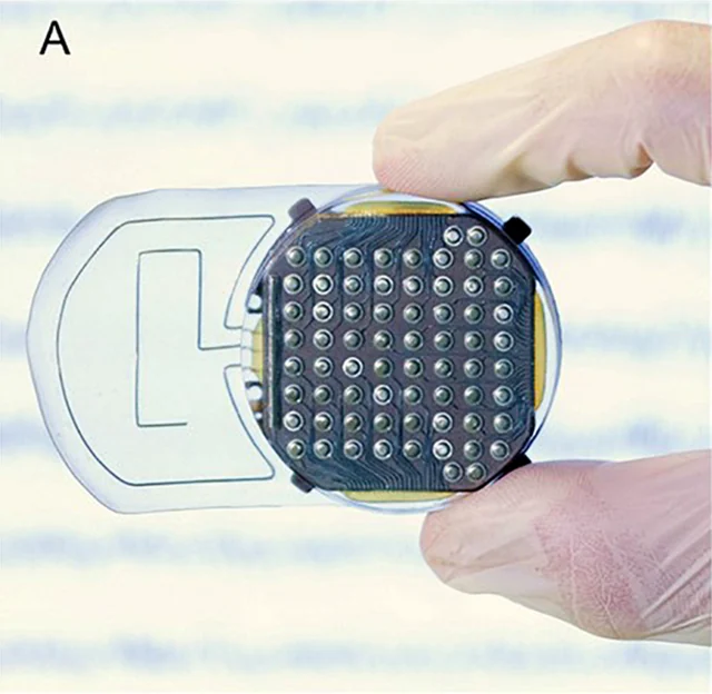
View the interface → Photograph BTSD-IMBCI-0004 WIMAGINE implant viewed from its cortical-contact side, held between gloved fingers.
WIMAGINE (CEA-Clinatec) epidural wireless ECoG implant A fully implanted, wireless epidural ECoG system developed by CEA-Clinatec for human motor BCI research, emphasizing clinical robustness and long-term stability over single-unit precision.
Ecog Human evidence
Photo credit Sauter-Starace et al., Frontiers in Neuroscience (2019), Fig. 1A · Frontiers · Figure 1A · CC BY 4.0 . Photographic panel cropped from the original figure; resized and re-encoded. Original scale bars and annotations retained.
View the interface → Photograph BTSD-PNI-0001 CWRU/Ardiem standard self-sizing spiral cuff: nominal 4 mm diameter and four radial contacts. It wraps a peripheral nerve.
CWRU/Ardiem spiral cuff - Design and sensory-study records
CWRU/Ardiem self-sizing spiral nerve cuff A foundational, non-penetrating, self-sizing peripheral nerve cuff electrode design family (spiral/helical cuff) widely used for chronic stimulation and sometimes low-SNR recording.
These sheets cover the same self-sizing cuff design family. The standard four-contact photograph appears once; the sensory study is a deployment record, not a second cuff architecture. The ITIS 33-contact prototype has its own catalog entry.
Pni Human evidence
Photo credit Photo courtesy of Ardiem Medical, Inc.; Christie et al., Journal of NeuroEngineering and Rehabilitation (2017), Figure 1 · JNER · Figure 1 · CC BY 4.0 . Whole published photograph re-encoded without cropping or upscaling. Original Ardiem attribution retained.
Related study records (1) FINE (Flat Interface Nerve Electrode) An extraneural cuff electrode that intentionally flattens/reshapes a peripheral nerve to bring fascicles closer to contacts, improving functional selectivity without penetrating the nerve.
Pni Human evidence
ActiGait implanted drop-foot stimulator (common peroneal nerve multi-contact cuff) A hybrid implanted-plus-external functional electrical stimulation (FES) system using a multi-contact cuff on the common peroneal nerve to restore ankle dorsiflexion during gait.
Pni Human evidence
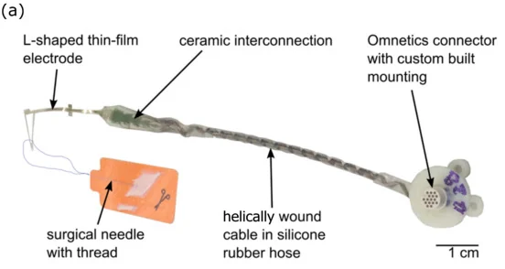
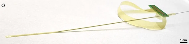
View the interface → Photograph BTSD-0006 TIME-4H assembly with thin-film electrode and helical lead; 1 cm scale retained.
TIME (Transverse Intrafascicular Multichannel Electrode) A flexible thin-film intrafascicular peripheral nerve interface inserted transversely through a nerve to access multiple fascicles, trading surgical complexity for selectivity.
Pni Human evidence
Photo credit Guiho et al., Sensors (2021), Fig. 2a · Sensors · Figure 2a · CC BY 4.0 . Photographic panel cropped from the original figure; resized and re-encoded. Original scale bars and annotations retained.
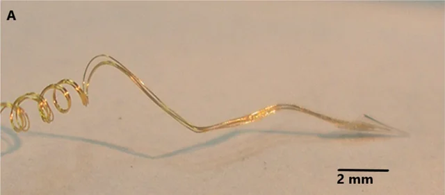
LIFE (Longitudinal Intrafascicular Electrode) A classic fine-wire intrafascicular peripheral nerve interface placed longitudinally within a fascicle for selective stimulation and compound action potential (CAP) recording.
Pni Human evidence
View the interface → Optical micrograph BTSD-IMBCI-0009 Neurotrophic cone-electrode assembly photographed under magnification; 2 mm scale retained.
Neurotrophic Electrode (Kennedy cone electrode) A biologically integrated intracortical electrode (hollow cone with microwires) designed to encourage neurite ingrowth for long-term single-unit recording in humans.
Intracortical Human evidence
Photo credit Gearing and Kennedy, Frontiers in Human Neuroscience (2020), Fig. 1A · Frontiers · Figure 1A · CC BY 4.0 . Photographic panel cropped from the original figure; resized and re-encoded. Original scale bars and annotations retained.
RPNI with implanted bipolar EMG electrodes (Vu 2023 configuration) A muscle-mediated peripheral nerve interface (RPNI) used as a biological signal amplifier: reinnervated muscle grafts generate stable, high-SNR EMG for long-term prosthetic control without chronic intraneural electrodes.
Pni Human evidence
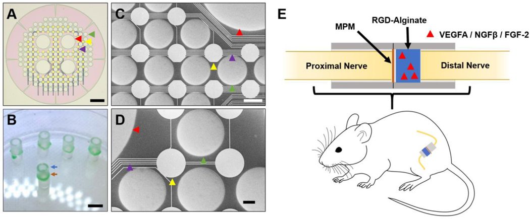
View the interface → Source figure · 2 views BTSD-PNI-0009-01 Redesigned mixed-porosity sieve, its assembly and microscopic contacts. Complete Figure 3.
Hyperflexible regenerative sieve electrode (Veith et al., 2021) A hyperflexible regenerative sieve electrode designed to promote neurovascular integration across a transected peripheral nerve interface (rat sciatic model).
Pni Research evidence
Photo credit Veith et al., Biomaterials (2021), Figure 3; © Elsevier Ltd. · Biomaterials · complete Figure 3 · © 2021 Elsevier Ltd. · source copyright retained . Complete PMC source figure copied intact, byte for byte. All panels, annotations and scale bars retained; no cropping, re-encoding, upscaling or synthetic enhancement.
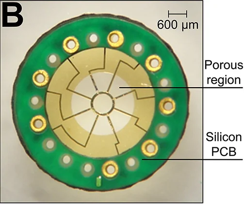
View the interface → Optical micrograph BTSD-PNI-0009-02 Optical micrograph of the fabricated macro-sieve electrode and bonded micro-PCB; 2016 configuration.
Macro-sieve regenerative electrode with transit zones (MacEwan et al., 2016) A chronically implanted macro-sieve electrode with large transit zones enabling robust axon regeneration and selective stimulation in a rat sciatic nerve transection model.
Pni Research evidence
Photo credit MacEwan, Zellmer, Wheeler, Burton & Moran, Frontiers in Neuroscience (2016), Figure 1B. DOI: 10.3389/fnins.2016.00557 · Frontiers · original figure · CC BY 4.0 . Photographic panel cropped from the original figure; resized and re-encoded. Original scale bars and annotations retained.
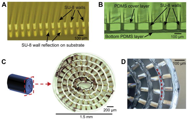
View the interface → Source figure · 2 views BTSD-PNI-0009-03 Microchannels and the rolled scaffold architecture. Complete Figure 3.
Microchannel-based regenerative scaffold interface (Srinivasan et al., 2015) A regenerative microchannel scaffold interface that guides axon regeneration into parallel channels and supports chronic recording/stimulation concepts (rat sciatic amputee model).
Pni Research evidence
Photo credit Srinivasan et al., Biomaterials (2015), Figure 3; © 2014 Elsevier Ltd. · Biomaterials · complete Figure 3 · © 2014 Elsevier Ltd. · source copyright retained . Complete PMC source figure copied intact, byte for byte. All panels, annotations and scale bars retained; no cropping, re-encoding, upscaling or synthetic enhancement.
Science biohybrid cortical engraftment implant (microwell / waffle device) A surface cortical biohybrid implant: optogenetically enabled neurons seeded in a microwell scaffold on cortex, with neurites integrating into the brain to transmit information via optical stimulation.
Ecog Preclinical evidence
Science neuronal-embedded electronic biohybrid interface (architecture concept) A company-described biohybrid architecture with neurons embedded in electronics; hardware geometry and complete-system performance remain not reported.
Other Theoretical evidence
Neural dust (ultrasonic backscatter mote) Ultrasonic recording mote: primary 2016 assemblies about 0.8 × 3 × 1 mm, one differential channel, 1.85-MHz interrogation and 10-kHz reconstructed signals. Rat nerve/muscle evidence; separate 1-mm-cube institutional claim.
Pni Preclinical evidence
View the interface → Source figure BTSD-ACAD-0002 Fabricated mesh electronics and their connection pads, shown across the complete photographic Figure 3.
Syringe-injectable mesh electronics Sub-micrometre-thick, centimetre-scale mesh electronics that unfold after injection through a needle as small as 100 µm. Harvard, 2015, in mouse brain.
Intracortical Preclinical evidence
Photo credit Schuhmann et al., Journal of Visualized Experiments (2018), Figure 3 · JoVE · complete Figure 3 · CC BY-NC-ND 3.0 . Complete source image retained byte-for-byte, including every panel and annotation. No cropping, re-encoding, recoloring or synthetic enhancement.
View the interface → Optical micrograph · 3 views BTSD-ACAD-0003 240-channel NeuroGrid surface array; 1 mm scale retained.
NeuroGrid (PEDOT:PSS surface array) A 4 µm thick organic electrode array with 10 × 10 µm sites on 30 µm pitch that records single-neuron action potentials from the brain surface. NYU and collaborators, 2015.
3D model available Ecog Research evidence
Photo credit Khodagholy et al., Science Advances (2016), Figure 1 · Science Advances · Figure 1A · CC BY-NC 4.0 . Photographic panel extracted from the published source; resized and re-encoded. Original scale bars and annotations retained; no hardware retouching.
Neurograins (wireless microimplant network) Distributed RF-powered neurograins: 650 × 650 × 250 µm chiplets, 1-kHz/8-bit recording, 48-node acute rat ensemble. Clear low-noise recordings came from a fraction of those channels; 770 is a projected network capacity.
3D model available Other Preclinical evidence
View the interface → Optical micrograph BTSD-ACAD-0005 Michigan carbon-fiber flex array, pictured in Huan et al. (2021): a related 2 × 8, 132µm-pitch configuration with sharpened PEDOT:pTS-coated tips, not the exact 2020 bare-carbon implant.
Carbon fiber electrode arrays (University of Michigan) Michigan carbon-fiber arrays: 2015 PEG or silicon-assisted cortical recording and 2020 flex arrays for separate-session unit and dopamine sensing. Coatings, pitch, supports and cohorts differ.
3D model available Intracortical Preclinical evidence
Photo credit Huan et al., Journal of Neural Engineering 18 (2021), Figure 1A. DOI: 10.1088/1741-2552/ac3dd7 · Original source · photographic panel · CC BY 4.0 . Photographic panel cropped from the original figure; resized and re-encoded. Original scale bars and annotations retained.
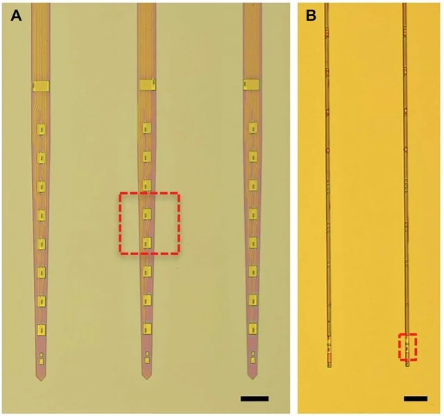
View the interface → Optical micrograph BTSD-ACAD-0006 As-fabricated NET-50 (left) and NET-10 (right) recording threads on their substrates, from the 2017 study. Scale bars: 100 µm and 50 µm, respectively.
Pictured: Nanoelectronic thread (NET) probes . Other family versions differ.
Nanoelectronic threads - Recording lineage and stimulation branch
StimNET ultraflexible stimulation thread Rice's 2023 32-contact polyimide stimulation/recording thread: 1 µm shank, reinforced sputtered-iridium-oxide contacts and separate bench and chronic mouse stimulation evidence.
StimNET is the latest documented branch here, designed for stimulation. Modular NET remains a distinct high-channel-count recording system.
Intracortical Preclinical evidence
Photo credit Luan, Wei, Zhao et al., Science Advances 3, e1601966 (2017), Figure 1A–B. DOI: 10.1126/sciadv.1601966 · Original source · physical interface · CC BY-NC 4.0 . Photographic panel cropped from the original figure; resized and re-encoded. Original annotations and scale bars retained where present.
Past versions and parallel branches (2) e-dura (electronic dura mater) A soft implant with the shape and elasticity of the dura that carries electrodes and drug channels. EPFL, 2015: cortical recording in free-moving rats and supported stepping after paralysis with spinal electrical stimulation, drug delivery and rehabilitation.
Ecog Preclinical evidence
Active flexible ECoG - Published hardware lineage
Active micro-ECoG array (196 sites, auditory cortex) A 14 x 14 multiplexed surface array with 196 platinum sites on 250 µm pitch and 29 interface wires on a roughly 25 µm film. Acute anesthetized rat auditory-cortex recordings, 2014.
The 2014 auditory-cortex configuration is the most recent documented design in this catalog, not a claim about present-day product availability.
3D model available Ecog Preclinical evidence
Past versions and parallel branches (1) Injectable micro-LED optoelectronics (wireless optogenetics) Cellular-scale GaN micro-LEDs with a Pt electrode and sensors on a thin injectable probe, used for fully wireless optogenetic control of freely moving animals. Illinois and Washington University, 2013.
Intracortical Preclinical evidence
Bioresorbable silicon brain sensors Wireless pressure and temperature sensors built from silicon that dissolves in the body, so no retrieval surgery is needed. Illinois, Washington University and Northwestern, 2016.
Other Preclinical evidence
Implantable wireless neural interface (Brown, 2013) A subcutaneous titanium-housed system that streams 100 channels of broadband cortical data wirelessly and charges through the skin. Brown University, tested in moving primates, 2013.
Intracortical Preclinical evidence
Head-mounted wireless neurosensor (Brown, 2014) External Brown2014 neurosensor: 96 neural channels plus auxiliary paths, 20 kS/s per channel, 46.1-g headstage and over48-hour reported runtime. Battery chemistry wording conflict retained; not a fully implanted package.
Intracortical Preclinical evidence
Dobelle cortical visual prosthesis A camera-driven visual cortex stimulator that gave blind volunteers phosphene images, built on a program that began in 1968. Reported by the Dobelle group in 2000.
Ecog Human evidence
Integrated-circuit microprobe (Wise, 1970) The first multielectrode microprobe made with integrated-circuit fabrication: gold electrodes on a silicon carrier, patterned by photoengraving. Wise, Angell and Starr, 1970. The root of the Michigan probe line.
Intracortical Research evidence
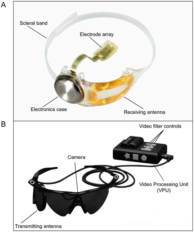
View the interface → Source figure BTSD-ACAD-0017 Argus II implant and retinal electrode array (A), with its external camera glasses and processing unit (B).
Argus II - Engineering and regulatory records
Argus II retinal prosthesis An epiretinal implant that sends camera-derived stimulation to a platinum electrode array tacked over the fovea. FDA humanitarian device approval in 2013; discontinued by its maker in 2019, leaving more than 350 users with an unsupported implant.
Two sheets document the same Argus II system. The implant gallery appears once on the engineering sheet; the other sheet records regulatory context.
Retinal Human evidence
Photo credit da Cruz et al., Ophthalmology (2016), Figure 1 · Ophthalmology · complete Figure 1 · CC BY-NC-ND 4.0 . Complete source image retained byte-for-byte, including every panel and annotation. No cropping, re-encoding, recoloring or synthetic enhancement.
Related system records (1) NEO wireless epidural BCI (Neuracle, Tsinghua) A battery-free epidural ECoG implant for hand function in cervical spinal cord injury, developed at Tsinghua and commercialized by Neuracle. Reported as the first implantable BCI to receive market approval, in China in 2026. China entry, secondary region.
Ecog Human evidence
Neuralink Blindsight Neuralink's visual prosthesis, which would stimulate visual cortex directly so that people without working eyes or optic nerves might perceive images. FDA breakthrough device designation in September 2024. Human results are not confirmed in the sources used here.
Intracortical Preclinical evidence
Beinao-1 (CIBR, NeuCyber) A wireless, fully implanted, semi-invasive BCI with a 128-channel flexible electrode matrix, from the Chinese Institute for Brain Research, Beijing and NeuCyber NeuroTech. Entered registered clinical trials in 2026. China entry, secondary region.
Ecog Human evidence
Auditory brainstem implant (ABI) A paddle electrode array placed on the cochlear nucleus of the brainstem to restore sound awareness when a cochlear implant cannot work. First implanted 1979, FDA approved in 2000 for NF2. The current US device has 21 platinum contacts on an 8.5 by 3.0 mm paddle.
Brainstem Human evidence
High-density subdural ECoG array with percutaneous connector (PMT array, Blackrock connector) A subdural grid of flat disk electrodes made by PMT, wired through the skull to a Blackrock percutaneous connector. Two published speech implants used it: 128 electrodes at 4 mm pitch in 2021 and 253 electrodes at 3 mm pitch in 2023.
Ecog Human evidence
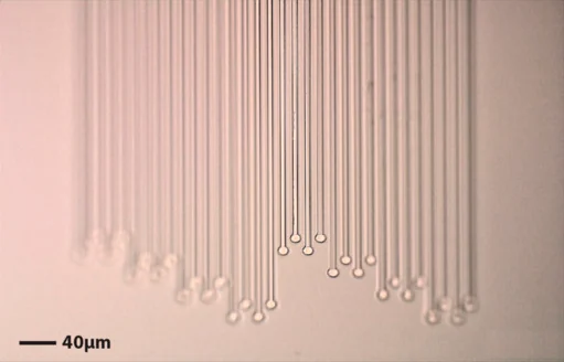
View the interface → Optical micrograph BTSD-ACAD-0043 NeuroRoots electrode tendrils and contacts under optical microscopy. Scale bar: 40 µm.
NeuroRoots (independent flexible electrode tendrils) Independent 7 µm wide, 1.5 µm thick electrode tendrils. The 2024 paper reports cerebellar single-unit recordings and at least seven weeks of rat recordings without repositioning.
Intracortical Preclinical evidence
Photo credit NeuroRoots study authors, APL Bioengineering (2024), Figure 1B, CC BY-NC 4.0 · Original source · photographic panel · CC BY-NC 4.0 . Photographic panel cropped from the original figure; resized and re-encoded. Original scale bars and annotations retained.
Sewing-machine polymer electrode threads (UCSF and Berkeley) A 2019 preprint system with 64 individually inserted polyimide-platinum threads, 16 µm shanks and one site per thread. Rat recordings exposed implant durability and tissue-response limits.
Intracortical Preclinical evidence
Modular polymer probe system (UCSF and Lawrence Livermore) Polyimide arrays with 16 contacts per shank and stackable 64-channel modules, supporting up to 1,024 recording channels in freely behaving rats. Neuron, 2019.
Intracortical Preclinical evidence
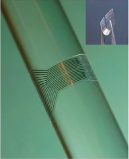
View the interface → Photograph BTSD-ACAD-0047 The real CLEAR graphene electrode array wrapped around a glass bar to demonstrate flexibility; 2014 device.
CLEAR transparent graphene micro-ECoG array A 16-site graphene surface array that combines electrical recording with light delivery and vascular imaging. Four graphene layers on parylene-C; rodent experiments, Wisconsin, 2014.
Ecog Preclinical evidence
Photo credit Park et al., Nature Communications 5, 5258 (2014), Figure 1c. DOI: 10.1038/ncomms6258 · Publisher · original figure · CC BY 4.0 . Photographic panel cropped from the original figure; resized and re-encoded. Original scale bars and annotations retained.
High-density transparent graphene array (UC San Diego) Transparent graphene surface arrays up to 256 channels with 20 µm contacts and platinum nanoparticles. Combined electrical and calcium imaging in mouse visual cortex, 2024.
Ecog Preclinical evidence
Abbott Liberta RC DBS system FDA-approved rechargeable DBS system from Abbott, approved by supplement S087 of PMA P140009 in January 2024. Many fields stay blank because the FDA record and company pages do not give them.
Dbs Human evidence
Abbott Proclaim XR spinal cord stimulation FDA-approved Abbott spinal cord stimulation family (Prodigy, Proclaim XR, Proclaim Plus, Externa), indications expanded to diabetic neuropathy and non-surgical back pain in 2023. Thin: hardware specs not in the FDA summary read.
Scs Human evidence
Advanced Bionics HiRes Ultra 3D cochlear implant FDA-approved cochlear implant with a 16-contact HiFocus electrode, specified from the manufacturer's surgeon manual and the FDA PMA record P960058. Clinical data not extracted yet.
Cochlear Human evidence
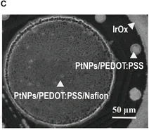
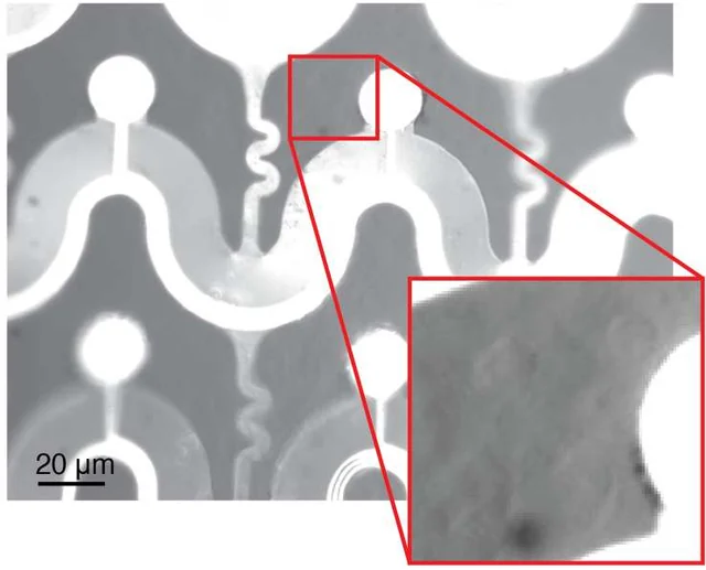
View the interface → Electron micrograph BTSD-ACAD-0098 The tissue-facing MultiTransm contact: a dopamine-sensing site surrounded by an IrOx reference ring. Original 50 µm scale retained.
AIR-CAS MultiTransm dual-mode MEA (dopamine plus electrophysiology) Two-shank silicon MEMS probe, 5.70 mm long, with 20 micrometer electrophysiology sites, a 180 micrometer dopamine-sensing site and an on-probe IrOx reference. Aerospace Information Research Institute (CAS) with Zhejiang University and Ruijin Hospital; recorded dopamine and spikes in mouse nucleus accumbens across sleep and wake (Research 2025).
Sensing Preclinical evidence
Photo credit Jia et al., Research (2025), Figure 2C · Research · Figure 2C · CC BY 4.0 . Complete SEM panel C selected from Figure 2, retaining its coating labels and 50 µm scale. Re-encoded without upscaling or hardware retouching.
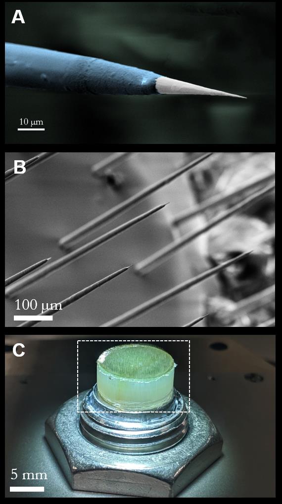
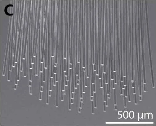
View the interface → Source figure BTSD-ACAD-0061 Argo microwire tip (A), electrode-tip array (B), and assembled bundle (C); the original scale bars are retained.
Argo microwire-CMOS recording system Paradromics/Caeleste's 2021 acute research system: a 65,536-pixel CMOS readout bonded to disordered PtIr wires, with 1,300-wire rat spiking and over 30,000 connected sheep surface channels kept separate.
Other Preclinical evidence
Photo credit Sahasrabuddhe et al., bioRxiv preprint (2020), Figure 2 · bioRxiv · complete Figure 2 · CC BY-NC-ND 4.0 . Complete source image retained byte-for-byte, including every panel and annotation. No cropping, re-encoding, recoloring or synthetic enhancement.
Axoft Fleuron ultrasoft neural probe Ultrasoft 128-channel depth probe from Axoft, tested for about 20 minutes in tissue due for resection in a first-in-human study in 2025. Preprint and company claims; not a chronic implant.
Intracortical Human evidence
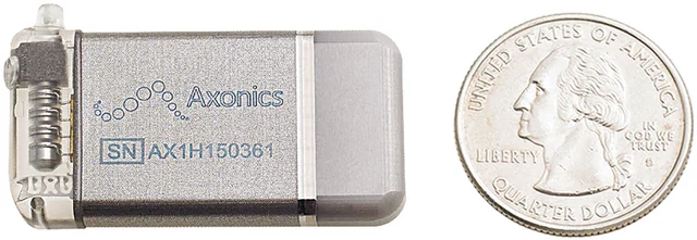
View the interface → Photograph BTSD-FDA-0011 Axonics sacral neuromodulation pulse generator beside a U.S. quarter, from the 2020 ARTISAN-SNM study. Lead not shown.
Axonics sacral neuromodulation FDA-approved rechargeable sacral neuromodulation system with a four-contact tined lead. Values come from the 2019 FDA summary for the fecal incontinence indication.
Pni Human evidence
Photo credit Benson et al., Neurourology and Urodynamics (2020), Figure 1, CC BY-NC 4.0. · Original source · physical interface · CC BY-NC 4.0 . Full image retained; resized and re-encoded. Original annotations and scale bars retained where present.
Bioness StimRouter PNS FDA-cleared peripheral nerve stimulation lead with an integrated receiver driven by an external transmitter, latest 510(k) read cleared February 2022. Thin: 510(k) text only.
Pni Human evidence
BISC wireless subdural CMOS array A 50 µm-thick wireless cortical chip with 65,536 physical electrodes and a selectable subset of up to 1,024 simultaneous channels. Published pig and non-human-primate recordings, December 2025.
Ecog Preclinical evidence
BlueWind Revi tibial neuromodulation FDA-authorized wirelessly powered tibial nerve stimulator for urgency incontinence, from the De Novo review and 2024 510(k). Trial result values were not extracted.
Pni Human evidence
Boston Scientific Vercise Genus DBS FDA-approved Vercise Genus DBS family with 8-contact and 16-contact directional leads and Multiple Independent Current Control. Values rest on the FDA overview and company pages; the SSED was not read.
Dbs Human evidence
Boston Scientific WaveWriter spinal cord stimulation FDA-approved Boston Scientific spinal cord stimulation family (Spectra WaveWriter, WaveWriter Alpha, Alpha Prime), with the SOLIS trial for patients without prior back surgery. Lead contact counts and IPG dimensions are not in the FDA summary read.
Scs Human evidence
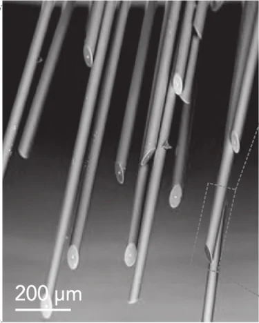
View the interface → Electron micrograph BTSD-ACAD-0069 The tissue-facing end of a CHIME glass-insulated microwire bundle, imaged by scanning electron microscopy. Scale bar: 200 µm.
CHIME glass-gold microwire CMOS interface, 2020 CHIME's glass-insulated gold wires and electroplated contacts coupled to MEA1k or camera-derived CMOS. Demonstrated bundles and connected pixels are separate from327,680 amplifier capacity; chronic validation remains open.
Intracortical Preclinical evidence
Photo credit Kollo et al., Frontiers in Neuroscience (2020), Fig. 2C detail, CC BY 4.0 · Frontiers · original figure · CC BY 4.0 . Select bottom central SEM inset of Figure 2C, retaining original 200 µm scale.
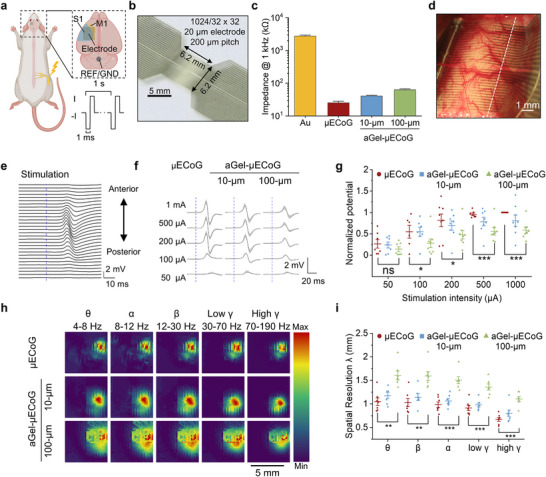
View the interface → Source figure BTSD-ACAD-0099 Figure 3 of the paper: photograph of the 1024-channel array (b, 5 mm scale) and of the array on exposed rat cortex (d, 1 mm scale), with schematic and data panels a, c and e to i.
CIBR aGel-µECoG adhesive-hydrogel micro-ECoG array 6 micrometer polyimide micro-ECoG (64 or 1024 channels, 20 micrometer sites at 200 micrometer pitch) coated with a thin adhesive PVA/PTPM hydrogel that sticks to the brain without sutures and resists fibrosis. Wu Ting's lab at CIBR Beijing with Qiu Dong at ICCAS; 16 weeks subdural in rats (Advanced Science 2025).
Ecog Preclinical evidence
Photo credit Chinese Institute for Brain Research (CIBR) group and collaborators, Advanced Science (2025), Figure 3 · Advanced Science · complete Figure 3 (CC BY 4.0) · CC BY 4.0 . Complete source image retained byte-for-byte as served by PubMed Central (546 px wide rendition). No cropping, re-encoding, recoloring or synthetic enhancement.
CIBR kirigami microelectrode array (ki-MEA) for primate brain Stretchable penetrating array whose electrode wires are cut like kirigami and form helical springs once implanted. 120-channel rodent and 256-channel macaque versions, 250 days of recording with over 240 neurons per session, about 1000 channels across arrays and a reach-decoding R2 of 0.79. Fang Ying's lab at CIBR Beijing (Nature Electronics, Feb 2026).
Intracortical Preclinical evidence
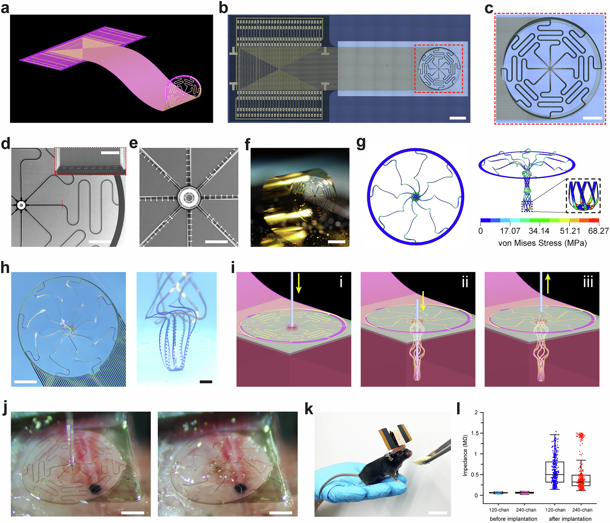
View the interface → Source figure BTSD-ACAD-0097 Figure 1 of the paper: the umbrella-type array and probe in micrographs and photographs (b to f, h, scale bars as published), photographs of the implanted array on mouse cortex (j) and a mouse with the implant (k, scale bar as published), with renderings, a simulation and impedance data in the remaining panels.
CIBR umbrella-type stretchable electrode array (USEs probe) 120- and 240-channel ultrathin (about 3 micrometer) polyimide and gold array of eight stretchable serpentine filaments joined to a central anchor, implanted in one pass on a 190 micrometer shuttle. Gao Lei's lab, Chinese Institute for Brain Research Beijing; same neuronal ensembles tracked in head-fixed mice for 80 weeks (Nature Communications 2026).
Intracortical Preclinical evidence
Photo credit Chinese Institute for Brain Research (CIBR) group and collaborators, Nature Communications (2026), Figure 1 · Nature Communications · complete Figure 1 · CC BY-NC-ND 4.0 . Complete source image retained byte-for-byte, including every panel and annotation. No cropping, re-encoding, recoloring or synthetic enhancement.
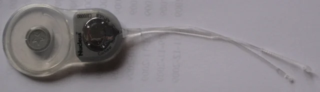
View the interface → Photograph BTSD-FDA-0012 Archival Nucleus specimen: Cochlear Freedom CI24RE receiver and electrode leads, photographed in 2009. Not the CI1000/Nexa generation.
Cochlear Nucleus implant system FDA-approved cochlear implant family, newest implant series CI1000 approved July 2025. Thinly sourced from the FDA supplement record and a Cochlear announcement; electrode specifications are not yet on the sheet.
Cochlear Human evidence
Photo credit Edwtie, Cochearimplants.JPG (2009), Wikimedia Commons, CC BY-SA 3.0. Cropped; the adapted photograph remains CC BY-SA 3.0. · Original source · photographic panel · CC BY-SA 3.0 . Photographic panel cropped from the original figure; resized and re-encoded. Original scale bars and annotations retained. The adapted photograph remains CC BY-SA 3.0.
Cortigent Orion visual cortical prosthesis Investigational 60-electrode cortical surface visual prosthesis from Cortigent, tested in a six-subject early feasibility study. Not FDA approved. Separate from the discontinued Argus II retinal implant.
Ecog Human evidence
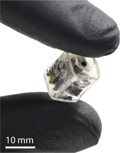
View the interface → Photograph BTSD-ACAD-0073 The packaged 2024 DOT epidural stimulator held between gloved fingers. Scale bar: 10 mm.
Pictured: DOT magnetoelectric epidural stimulator, 2024 . Other family versions differ.
DOT magnetoelectric platform - Research prototype and clinical program
Motif DOT magnetoelectric brain stimulator Pea-sized, battery-free wireless cortical stimulator from Motif Neurotech, shown acutely in a human in 2023 and now in an early feasibility study for treatment-resistant depression.
The photograph documents the 2024 research prototype. The Motif program is a separate clinical record; this image does not establish its later implant geometry.
Other Human evidence
Photo credit Woods, Singer et al., Science Advances (2024), Fig. 1A detail, CC BY 4.0 · Publication · original figure · CC BY 4.0 . Photo component selected from original PDF-embedded Figure 1A; original 10 mm scale retained. Resized and re-encoded; no hardware retouching.
Related platform records (1) Endocisternal catheter and ME interface, 2023-2024 Catheter electrodes navigated through cerebrospinal-fluid spaces, coupled to magnetoelectric bioelectronics. Full 2023 preprint specifications are separated from the 2024 published abstract and supplement.
Other Preclinical evidence
View the interface → Optical micrograph BTSD-ACAD-0059 The fenestrated tissue-facing Flex2Chip array with cerebellar cells in the same focal plane. Scale bar: 20 µm. The source inset has adjusted brightness and contrast.
Flex2Chip flexible-array CMOS interface Capillary-assembled suspended pads connect flexible neural arrays to a CMOS-MEA. Published 720/2,200-connection layouts, 1,024 simultaneous chip channels and acute 504-site ECoG use are kept distinct.
Ecog Preclinical evidence
Photo credit Zhao et al., Science Advances (2023), Fig. 4A, CC BY-NC 4.0 · Original source · physical interface · CC BY-NC 4.0 . Photographic panel cropped from the original figure; resized and re-encoded. Original annotations and scale bars retained where present.
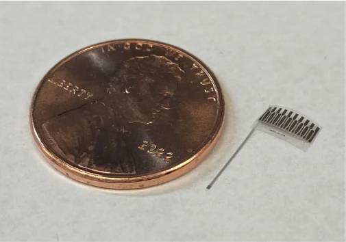
View the interface → Photograph BTSD-ACAD-0053 The released flexible neurochemical and recording probe, beside a US penny for scale.
Flexible neurochemical-release and recording probe (CMU and Pittsburgh) Parylene C probe with 16 recording contacts and two electrically actuated chemical-release sites. Acute rat proof of concept, with finite drug loading, stimulation artifacts and chronic-use work still open.
Intracortical Preclinical evidence
Photo credit Malekoshoaraie et al., Microsystems & Nanoengineering (2024), Fig. 2a, CC BY 4.0 · Publisher · original figure · CC BY 4.0 . Select only photo panel 2a; no recoloring, geometry alteration or invented background. Penny retained as scale.
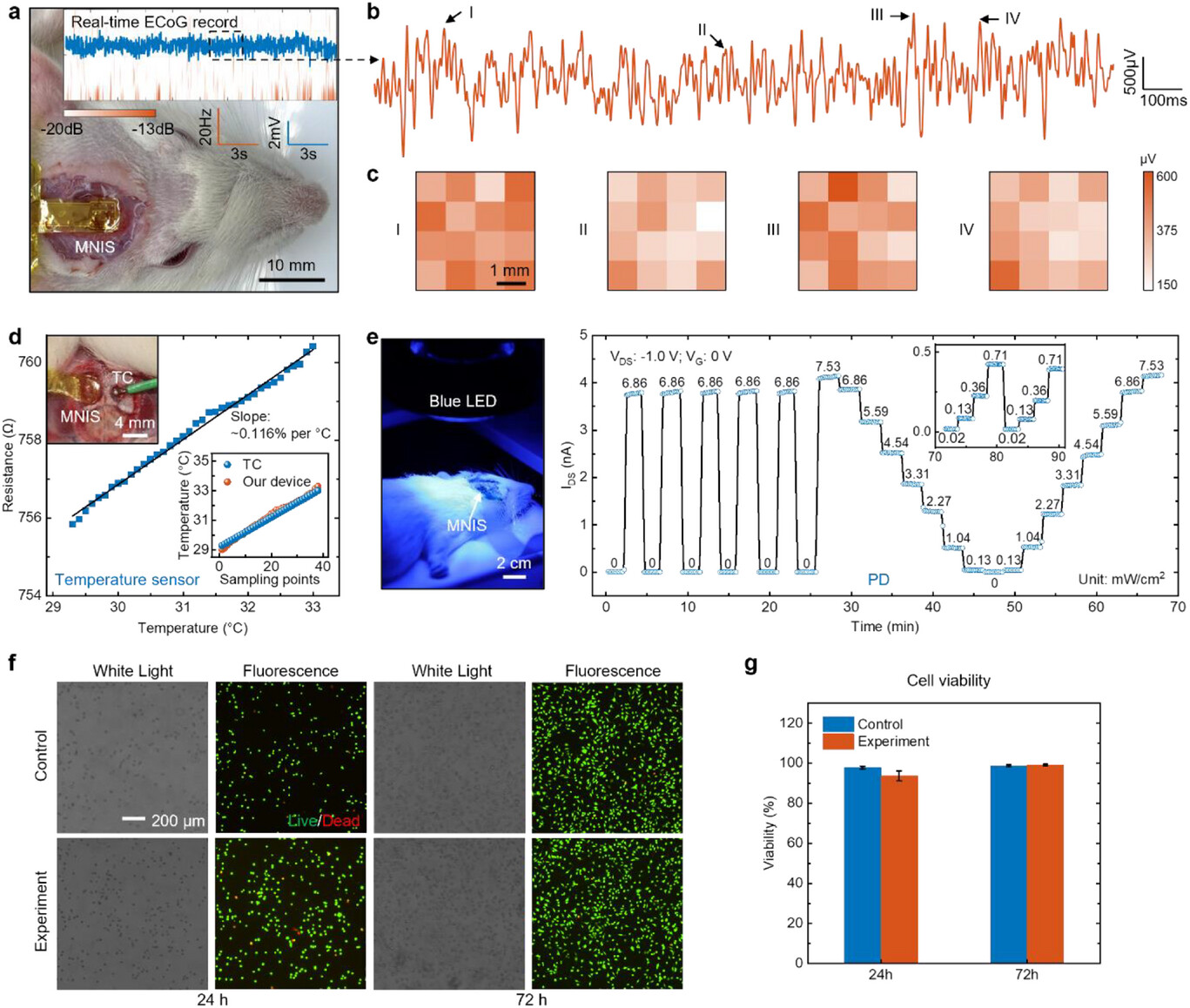
View the interface → Source figure BTSD-ACAD-0100 Figure 4 of the paper: photographs of the implanted device on a rat (a, 10 mm scale; d inset, 4 mm; e, 2 cm) alongside recording, temperature, photodetector and cell-viability data. Panels b, c, d, f and g are data plots and micrographs rather than device photographs.
Fudan MNIS active silicon-transistor multimodal cortical interface 4 x 4 array of silicon PMOS transistor nodes on a 31 micrometer flexible film that records ECoG by capacitive coupling, senses temperature with gold resistors and detects light with built-in photodiodes. Song Enming's group at Fudan University; acute rat recordings (Advanced Science 2025).
Ecog Preclinical evidence
Photo credit Song group and collaborators, Fudan University, Advanced Science (2026), Figure 4 · Advanced Science · complete Figure 4 (CC BY 4.0) · CC BY 4.0 . Complete source image retained byte-for-byte, including every panel and annotation. No cropping, re-encoding, recoloring or synthetic enhancement.
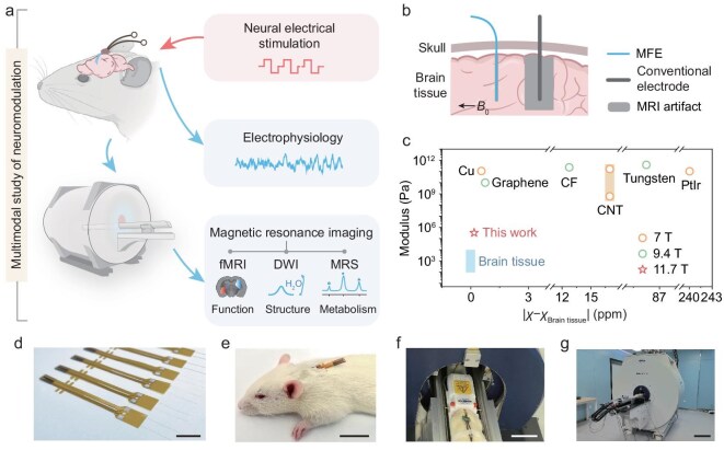
View the interface → Source figure BTSD-ACAD-0109 Figure 1 of the paper: photographs of the fibre electrode array (d), a rat carrying the implant (e), the animal in the MRI bed (f) and the scanner (g), with schematic and plot panels a to c. Scale bars as published.
Fudan MRI-compatible PEDOT:PSS fiber electrode (MFE) Wet-spun PEDOT:PSS fibre about 15 micrometers across with PDMS insulation and a magnetic susceptibility of -9.23 ppm matched to brain tissue, giving little to no artifact at 11.7 T. 11.9 kOhm at 1 kHz for a 20 micrometer fibre, charge injection limit 14.3 mC/cm2, used to stimulate and record in rats during multimodal MRI. Fudan University (National Science Review 2026).
Intracortical Preclinical evidence
Photo credit Fudan University group, National Science Review (2026), Figure 1 · National Science Review · complete Figure 1 (CC BY 4.0) · CC BY 4.0 . Complete source image retained byte-for-byte as served by PubMed Central (661 px wide rendition). No cropping, re-encoding, recoloring or synthetic enhancement.
Two-film ME stimulators - Two configurations in one 2020 study
Fully implanted two-film PZT ME stimulator, 2020 Two PZT/Metglas films, discrete rectifiers and a bias magnet in a 175-mm³ package drive rat MFB place preference. Acute behavioral evidence is separate from the PVDF Parkinson headstage.
The fully implanted PZT assembly is highlighted. The external PVDF headstage is a different configuration, not an earlier publication or an obsolete product.
Dbs Preclinical evidence
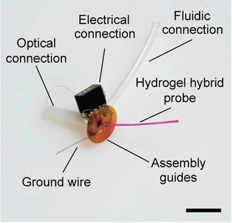
Past versions and parallel branches (1) View the interface → Photograph BTSD-ACAD-0054 The hydrogel-hybrid fiber assembly, with a 1 cm scale bar. The hydrogel is dyed pink for visibility in the source photograph.
Hydrogel-hybrid multifunctional fiber probe (MIT) Thermally drawn optical, electrical and fluidic fibers integrated in a soft hydrogel matrix. Dry insertion and hydrated compliance, with six-month mouse recordings and a connectorization limit that prevents independent readout of every microwire.
Intracortical Preclinical evidence
Photo credit Park et al., Nature Communications (2021), Fig. 1e, CC BY 4.0 · Publisher · original figure · CC BY 4.0 . Select source photo panel 1e only, with original labels and scale; no hardware editing.
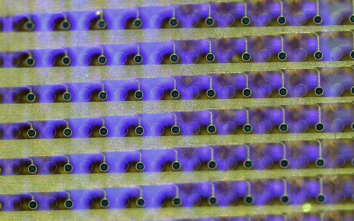
View the interface → Optical micrograph · 2 views BTSD-ACAD-0052 Physical contacts, traces and illuminated microLEDs of the small-format iEEG microdisplay.
iEEG microdisplay with PtNR recording grid PtNR surface electrodes laminated with GaN microLEDs to display cortical activity in the surgical field. Rat and pig proof of concept, including a 2,048-pixel display over 1,024 recording contacts and documented electrical interference.
Ecog Preclinical evidence
Photo credit University of California San Diego · UC San Diego · microdisplay close-up · Institutional press-image permission · credit required . Complete source image retained byte-for-byte, including every panel and annotation. No cropping, re-encoding, recoloring or synthetic enhancement.
View the interface → Photograph BTSD-STUP-0003 INBRAIN graphene cortical array held with tweezers. Archival manufacturer photograph; source-image metadata dates to 2022, and the exact hardware revision is unspecified.
INBRAIN graphene cortical interface Thin-film graphene cortical surface interface from INBRAIN, used intraoperatively in a first-in-human study at Manchester. Company release; contact counts not published in the sources read.
Ecog Human evidence
Photo credit INBRAIN Neuroelectronics / Graphene Flagship, via EurekAlert! · Original source · physical interface · Public Domain — source-declared . Resized/re-encoded for web display only.
Inspire upper airway stimulation FDA-approved hypoglossal nerve stimulator for obstructive sleep apnea, newest version Inspire V approved August 2024. Thinly sourced from the FDA overview and supplement record; many cells stay blank.
Pni Human evidence
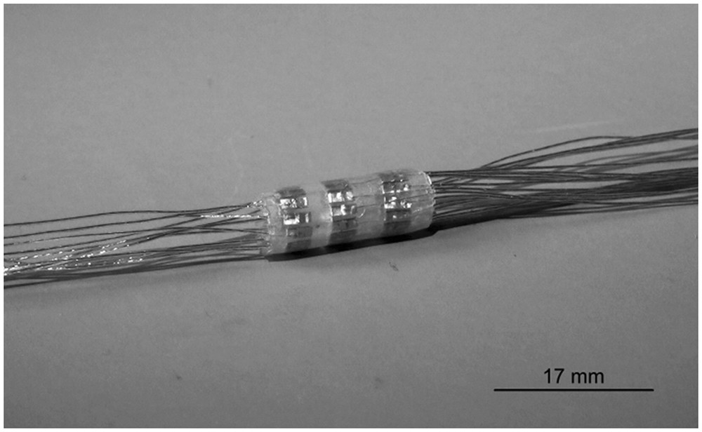
View the interface → Photograph BTSD-PNI-0012 ITIS/Ljubljana’s manufactured 33-contact spiral cuff, with contact rows visible through its sheath. Original 17 mm scale retained.
ITIS/Ljubljana 33-contact spiral cuff (2018 research prototype) A separate 33-contact platinum spiral-cuff prototype, photographed with its contact rows visible. Developed by the ITIS/Ljubljana team and tested on isolated porcine vagus nerve.
Pni Research evidence
Photo credit Rozman, Pečlin, Ribarič, Godec and Burja, Scientific Reports (2018), Figure 4 · Scientific Reports · manufactured cuff photograph · CC BY 4.0 . Complete published photograph copied intact, byte for byte, including its original scale bar.
LivaNova VNS Therapy SenTiva FDA-approved vagus nerve stimulation system for refractory epilepsy with the SenTiva generator that senses heart rate. Values come from the FDA supplement records, summary and LivaNova's spec sheet.
Pni Human evidence
View the interface → Photograph BTSD-ACAD-0072 Six magnetoelectric-powered spinal stimulators with their electrode leads. Authors' preprint prototype photograph, 2024. Scale bar: 1 cm.
Magnetoelectric network spinal stimulators, 2025 2025 network's spinal configuration: roughly 1-cm³ wireless battery-free IPGs, one electrode pair per node, six bench devices and up to four in acute pigs. LED/power/pacing demonstrations are not merged into that cohort.
Scs Preclinical evidence
Photo credit Woods, Alrashdan et al., Research Square preprint (2024), Fig. 3a, CC BY 4.0 · Original source · photographic panel · CC BY 4.0 . Photographic panel cropped from the original figure; resized and re-encoded. Original scale bars and annotations retained.
MagNI current-controlled ME implant, 2020 Published 8.2-mm³, 28-mg MagNI research stimulator: 250-kHz ME power, 1.5-mm² ASIC and programmable biphasic current. Hydra activation and a seven-day saline test are not spinal pain treatment.
Pni Preclinical evidence
View the interface → Photograph BTSD-ACAD-0071 The encapsulated ME-BIT implant in its clear delivery sheath. Scale bar: 2 mm.
ME-BIT magnetoelectric nerve stimulator, 2022 2022 magnetoelectric-powered stimulation ASIC and packaged ME-BIT variants. Rodent direct contact, pig vascular leads and device delivery remain separate; chronic packaging, thrombosis and exposure-standard limits are explicit.
Endovascular Preclinical evidence
Photo credit Chen et al., Nature Biomedical Engineering (2022), Fig. 1d, CC BY 4.0 · Publisher · original figure · CC BY 4.0 . Select photo panel 1d only, retaining original rounded outline and 2 mm scale.
MED-EL cochlear implant system FDA-approved cochlear implant family with SYNCHRONY 2 as the current implant, indications expanded in October 2024. Values come from the FDA summary of safety and effectiveness; electrode specs are not on this sheet yet.
Cochlear Human evidence
Medtronic Inceptiv closed-loop SCS FDA-approved Medtronic spinal cord stimulator with closed-loop ECAP sensing, approved April 2024. Values rest on the FDA supplement record and Medtronic's announcement; the SSED was not read.
Scs Human evidence
Medtronic Percept and SenSight DBS FDA-approved deep brain stimulation family with sensing-enabled Percept neurostimulators and 8-contact SenSight directional leads. Values are scoped to the FDA record, Medtronic labeling and an independent technical report.
Dbs Human evidence
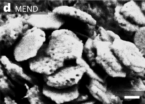
View the interface → Electron micrograph BTSD-ACAD-0080 Electron micrograph of the fully coated MEND nanodiscs. Scale bar: 100 nm. These are injected nanomaterials, not a conventional electrode implant.
MEND magnetoelectric nanodiscs, 2024 Injected Fe3O4-CoFe2O4-BaTiO3 nanodiscs mediate magnetic neuromodulation in mice. No ASIC, lead, recording uplink or stimulation transgene; optical verification uses a separate reporter.
Other Preclinical evidence
Photo credit Kim et al., Nature Nanotechnology (2024 online), Fig. 1d, CC BY 4.0 · Publisher · original figure · CC BY 4.0 . Select SEM panel 1d only and retain original MEND label and 100 nm scale.
View the interface → Optical micrograph · 2 views BTSD-ACAD-0087 Ultraflexible MERF recording shanks; 1 mm scale retained.
MERF 128-channel ultraflexible polyimide array (CEBSIT) Two-shank, 128-channel, 1 micrometer thick polyimide array from Zhao Zhengtao's group at CEBSIT (Chinese Academy of Sciences) with Li Chengyu's group at Lingang Laboratory. Chronic single-unit recording in macaque visual and motor cortex for up to eight months, plus a cursor-control demonstration.
Intracortical Preclinical evidence
Photo credit Tian et al., Advanced Science (2023), Figure 1b · Advanced Science · Figure 1b · CC BY 4.0 . Photographic panel rendered directly from the published PDF in its original colors, cropped and re-encoded. Original scales retained; no retouching or synthetic enhancement.
Mindtrix cortical visual reconstruction system Mindtrix's cortical stimulation system for visual reconstruction in blindness, with a first investigator-initiated human study reported in December 2025. Sources are Chinese-language press and the company site; study hardware is not fully described.
Ecog Human evidence
MIT all-polymer drawn fibers - Published hardware lineage
MIT graphite-polymer multifunctional fiber, 2017 Graphite-doped polymer electrodes, one optical waveguide and two fluidic channels within a drawn fiber. The selected experimental section was 200 micrometers despite a less-than-200 claim elsewhere in the paper.
The 2017 graphite-polymer design develops the 2015 all-polymer fiber. Tin-wire and hydrogel-hybrid devices are different architectures, not hidden revisions.
Intracortical Preclinical evidence
Past versions and parallel branches (1) MIT thermally drawn tin multielectrode fiber, 2015 Tin electrodes in a polymer fiber, with sacrificial-cladding removal reducing the demonstrated cross-section from 416 to 85 micrometers. Recording-only architecture is distinct from the all-polymer optical/fluidic fiber.
Intracortical Preclinical evidence
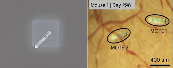
View the interface → Optical micrograph BTSD-ACAD-0081 MOTE on a salt crystal (left), and implanted MOTEs in mouse cortex at day 296 (right); 400 µm scale retained.
MOTE optical tetherless recorder, 2025 Subnanolitre electrical recorder with AlGaAs optical power and PPM uplink. Mouse evidence uses a cranial window and head fixation; day-365 LFP is weakened and averaged.
Intracortical Preclinical evidence
Photo credit KAIST · KAIST · original research press image · Institutional press-image permission · credit retained . Complete source image retained byte-for-byte, including every panel and annotation. No cropping, re-encoding, recoloring or synthetic enhancement.
Nalu neurostimulation system PNS FDA-cleared miniature peripheral nerve stimulator powered by a worn Therapy Disc, cleared 2019 with later 510(k)s through 2024. Thin: 510(k) text only.
Pni Human evidence
Nankai / Rongyuan interventional (stent-electrode) BCI Endovascular stent-electrode BCI from Duan Feng's group at Nankai University, with a subcutaneous wireless power and transmission unit. Sheep (2022), non-human primate (2023), sensor retrieval in sheep (2024) and a first human implant in a stroke patient (2025). Electrode geometry and materials are not published in the sources read.
Endovascular Human evidence
NeuroPace RNS System FDA-approved responsive neurostimulator that records ECoG through four-contact cortical strip and depth leads and delivers stimulation when programmed detections fire. Values come from the FDA summary and the published trials, scoped to the 2013 RNS-300M approval.
Ecog Human evidence
Neuros Altius HFAC nerve block FDA-approved implanted nerve cuff system that blocks pain from an amputated limb with 5 or 10 kHz alternating current, approved August 2024. Values come from the FDA summary of safety and effectiveness.
Pni Human evidence
NeuroString stretchable neurochemical sensor (Stanford) Graphene/nanoparticle networks embedded in elastomer for monoamine sensing in brain and gut. Chemical measurements, not spike recording; brain and gut layouts, calibration and clinical limits remain distinct.
Sensing Preclinical evidence
View the interface → Optical micrograph BTSD-ACAD-0065 The recording ends of Neurotassel filaments under optical microscopy. Scale bar: 50 µm; electron-micrograph inset: 10 µm.
Neurotassel elastocapillary filament arrays China-secondary coverage: 2019 polyimide filaments self-assembled in dissolvable PEG; 16-channel chronic mouse evidence is separate from 128-1,024-channel fabrication and preliminary recording claims.
Intracortical Preclinical evidence
Photo credit Guan, Wang, Gu et al., Science Advances (2019), Fig. 1B, CC BY-NC 4.0 · Original source · physical interface · CC BY-NC 4.0 . Photographic panel cropped from the original figure; resized and re-encoded. Original annotations and scale bars retained where present.
NeuroXess 256-channel flexible ECoG BCI NeuroXess's 256-channel flexible cortical-surface array used for real-time motor and Mandarin speech decoding at Huashan Hospital. Reported in temporarily implanted epilepsy and tumor patients; some figures are company announcements.
Ecog Human evidence
NeuroXess Triple-F fully implanted subdural BCI NeuroXess's fully implanted, fully wireless subdural BCI with a chest-pocket battery, in a registration trial at Huashan Hospital since July 2026. Most figures are company disclosures from Chinese-language sources.
Ecog Human evidence
Nevro Senza HFX iQ SCS FDA-approved 10 kHz spinal cord stimulation system with a 16-channel rechargeable IPG, approved October 2022. Values rest on the FDA supplement record and Nevro's prescriber information; the SSED and clinical data were not read.
Scs Human evidence
Nurotron WH-01A auditory brainstem implant (Shanghai Ninth People's Hospital) Domestic Chinese auditory brainstem implant with 16 electrodes on a 5.5 x 3.5 mm silicone paddle, developed from Wu Hao's team at Shanghai Ninth People's Hospital. First implant January 26, 2022; NMPA innovative-device special review entry March 2024 (company report); phase III NF2 trial registered.
Brainstem Human evidence
ONWARD ARC-IM implantable spinal stimulation Investigational implantable epidural spinal stimulation system for blood pressure instability after spinal cord injury, in the Empower BP pivotal study. Hardware specifications are not published in the sources read.
Scs Human evidence
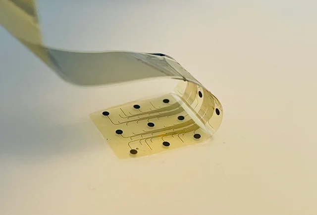
View the interface → Photograph BTSD-ACAD-0051 A flexible PtNRGrid cortical recording sheet held between fingers.
PtNRGrid platinum-nanorod surface arrays Reconfigurable cortical grids with 30 µm platinum-nanorod contacts in 6.6 µm parylene C. The 2022 paper reports 1,024- and 2,048-channel layouts with different pitch and coverage; a later IDE announcement is not commercial clearance.
3D model available Ecog Human evidence
Photo credit David Baillot / UC San Diego Jacobs School of Engineering · UC San Diego · official press photograph · Institutional press-image permission · credit required . Complete source image retained byte-for-byte, including every panel and annotation. No cropping, re-encoding, recoloring or synthetic enhancement.
PUF-addressed ME multisite stimulator, 2021-2022 Rice-led 180-nm CMOS ME stimulation configuration with eight-bit PUF addresses and a shared transmitter. Bench and Hydra multisite demonstrations stay separate from rat nerve stimulation and proposed cardiac/spinal use.
Pni Preclinical evidence
Saluda Evoke closed-loop SCS FDA-approved closed-loop spinal cord stimulator that records ECAPs through two 12-contact leads, approved February 2022. Values come from the FDA summary of safety and effectiveness.
Scs Human evidence
View the interface → Optical micrograph BTSD-STUP-0004 2 mm PRIMA photovoltaic retinal implant from the 2020 preclinical study. Dimension arrow retained.
Science PRIMA subretinal photovoltaic implant Subretinal 378-pixel photovoltaic implant with near-infrared camera glasses for geographic atrophy, with a 38-participant European study published in NEJM in October 2025.
Retinal Human evidence
Photo credit Muqit et al., PLOS ONE15(4):e0230713 (2020), Figure2 · Original source · physical interface · CC BY 4.0 . Right-hand photographic panel cropped; dimension marker preserved; resized/re-encoded for display.
SCOPe subdural CMOS optical probe Wired CMOS fluorescence imager and microLED stimulator with lensless reconstruction. Published abstract, supplement and 2023 preprint are distinguished; no wireless or single-cell claim.
Other Preclinical evidence
Self-rectifying magnetoelectric metamaterial, 2023 Rice-led semiconductor-coated ME laminates for millisecond-timed peripheral stimulation. Schottky and p-Si/ZnO variants, low fabrication yield, short encapsulation life and external trigger hardware remain explicit.
Pni Preclinical evidence
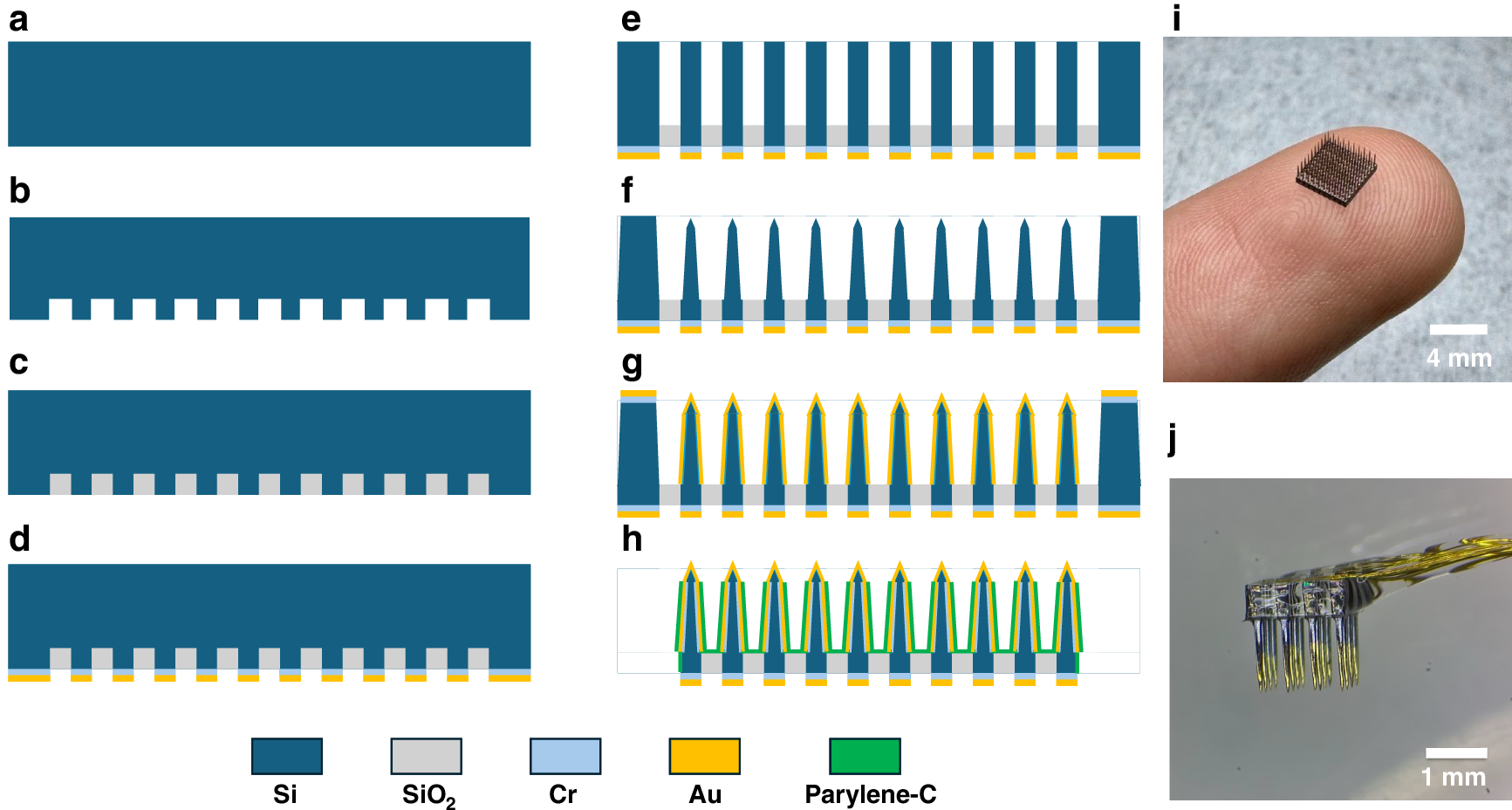
View the interface → Source figure BTSD-ACAD-0103 Fabrication process (a to h, schematics) and photographs of the completed array (i, 4 mm scale) and a packaged array (j, 1 mm scale), shown across the complete Figure 1.
Semi CAS silicon microneedle array with local de-insulation 10 x 10 bulk-silicon microneedle array, Utah-style, with tips exposed by masking in PDMS before Parylene-C deposition instead of etching. Tip exposure about 50 um, platinum black sites at 33.2 kOhm at 1 kHz, 15 of 16 channels recording in rat with mean spike SNR 12.63. Pei Weihua's group, Institute of Semiconductors, CAS.
Intracortical Preclinical evidence
Photo credit Pei group, Institute of Semiconductors CAS, Microsystems & Nanoengineering (2025), Figure 1 · Microsystems & Nanoengineering · complete Figure 1 · CC BY-NC-ND 4.0 . Complete source image retained byte-for-byte, including every panel and annotation. No cropping, re-encoding, recoloring or synthetic enhancement.
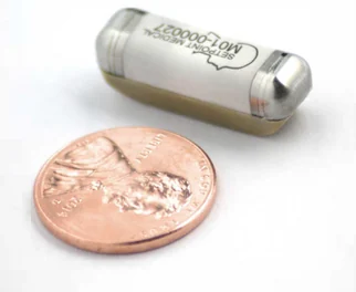
View the interface → Photograph BTSD-FDA-0010 SetPoint's implanted pulse generator, shown beside a coin for scale. RESET-RA study device, 2024.
SetPoint vagus nerve stimulation for rheumatoid arthritis FDA-approved vagus nerve stimulator for rheumatoid arthritis, approved July 2025. Values come from the FDA summary of safety and effectiveness; trial efficacy numbers were not extracted.
Pni Human evidence
Photo credit Peterson et al., Bioelectronic Medicine (2024), Figure 2A, CC BY 4.0. Cropped from the original figure. · Publication · original figure · CC BY 4.0 . Photographic panel cropped from the original figure; resized and re-encoded. Original scale bars and annotations retained.
Shenfu Jianxing brain-spine interface (Fudan) Fudan's brain-spine interface from Shenfu Jianxing: brain electrodes decode intent and drive spinal epidural stimulation in paraplegia. Four patients in a 2025 investigator-initiated study. Hardware specifications are not published; sources are Chinese-language releases and the ChiCTR registry.
Other Human evidence
SIAT ferroelectric bioelectronic interface (FBI) for vagus nerve Self-curling, suture-free hydrogel cuff for a 0.5 mm vagus nerve carrying a carbon nanotube and P(VDF-TrFE) ferroelectric strip that turns near-infrared light into nerve-like electrical pulses. Du Xuemin's group at SIAT; anti-inflammatory vagus modulation in rats (Advanced Materials, 2026).
Pni Preclinical evidence
SIAT laser-induced graphene multimodal physiological-electrophysiological electrodes Two laser-induced graphene devices from Lu Yi's group at SIAT and SIBS: a stretchable BiL-LIG wearable sensor and an IntE-LIG neural electrode array with a conductive polymer-gold coating, 1 kHz impedance down 98.5%, 4 weeks of macaque and 12 weeks of mouse recording, with a mouse seizure closed loop.
Ecog Preclinical evidence
SIAT liquid-crystal MXene/PEDOT:PSS fibre electrode Wet-spun fibre electrode in which MXene nanosheets are aligned in a nematic liquid-crystal state, with an MXene/PEDOT:PSS composite version. Du Zhanhong's lab at SIAT: 43.16 ohm mm2 at 1 kHz, 11.81 mC/cm2 charge injection, cortical recording in mouse and deep brain stimulation in rat.
Other Preclinical evidence
SIAT NeuroWorm movable fibre electrode 60-channel, 196 micrometer stretchable fibre rolled from an ultrathin film, with a magnetic tip so an external field can steer it inside rabbit brain or rat muscle. Shenzhen Institute of Advanced Technology, Nature 2025; muscle recordings beyond 43 weeks.
Other Preclinical evidence
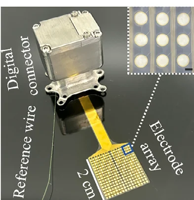
View the interface → Photograph BTSD-ACAD-0090 Integrated 256-channel µECoG implant with its surface array, reference lead and titanium electronics enclosure.
SIMIT 256-channel high-density micro-ECoG (64 electrodes/cm2) 16 x 16 gold-on-polyimide micro-ECoG array with 850 micrometer sites at 1250 micrometer pitch, in a titanium-housed implant with four Intan chips. 203 days in a Labrador, then intraoperative and short-term human motor-imagery decoding at Huashan Hospital. SIMIT with NeuroXess.
Ecog Human evidence
Photo credit Zhou et al., Advanced Science (2025), Figure 1b · Advanced Science · Figure 1b · CC BY 4.0 . Photographic panel extracted from the published source; resized and re-encoded. Original scale bars and annotations retained; no hardware retouching.
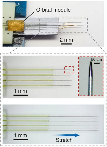
View the interface → Photograph · 2 views BTSD-ACAD-0088 Implant module and adjustable insertion shuttles; original 2 mm, 1 mm and 50 µm scales retained.
SIMIT mosquito-mouthpart bionic neural probe (128-channel flexible array) 128-channel, 2.5 micrometer polyimide array delivered through the dura by sharpened tungsten shuttles in microtubule tracks, with a tactile sensor array that warns of vessels. Built by Tao Hu and Wei Xiaoling's group at Shanghai Institute of Microsystem and Information Technology; mouse recordings to 16 weeks.
Intracortical Preclinical evidence
Photo credit Zhou et al., Microsystems & Nanoengineering (2023) · Microsystems & Nanoengineering · Figure 2b · CC BY 4.0 . Figure 2b photographic panel rendered directly from the original PDF in its original colors and re-encoded; no cropping of the panel, scale removal or hardware retouching.
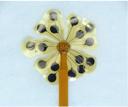
View the interface → Photograph · 2 views BTSD-ACAD-0089 Unfolded intraventricular electrode, with conformal petals and surface contacts.
SIMIT silk-enabled intraventricular interface (IVI) Catheter-delivered 14 micrometer polyimide microelectrode array on a shape-memory silk fibroin scaffold that unfolds in cerebrospinal fluid and lies on the inner surface of the lateral ventricle. SIMIT and NeuroXess; recorded from the caudate head in Parkinsonian sheep for four weeks.
Other Preclinical evidence
Photo credit Liang et al., Nature Communications (2025), Figure 1 · Nature Communications · Figure 1e, lower photograph · CC BY 4.0 . Photographic panel extracted from the published source; resized and re-encoded. Original scale bars and annotations retained; no hardware retouching.
SINANO neuron-scale all-hydrogel fibre electrode array 16-channel array of PEDOT:PSS hydrogel fibres wet-spun and annealed under mechanical constraint to 0.94 to 20 micrometer diameter, the size of a neuron. Single-unit tracking for 6 months in mouse motor cortex, no clear gliosis at 16 weeks. Zhang Ting's group at Suzhou Institute of Nano-Tech and Nano-Bionics (Matter, 2026).
Intracortical Preclinical evidence
SJTU implantable nanoscale neural probe (INNP) for in vivo intracellular recording Probe with a tip about 100 nm across and a sensing region exposed over about 40 nm, so only the tip site sits inside one neuron. Records intracellular action potentials up to about 70 mV and synaptic currents in live mouse. Liu Jingquan's group at Shanghai Jiao Tong University (IEEE MEMS 2026 award paper).
Intracortical Preclinical evidence
SJTU opto-electrophysiology nanotube probe with total-internal-reflection layer Laser-pulled nanotube probe with a nano optical fibre as the light channel inside and iridium oxide as the electrical channel outside, plus a total-internal-reflection layer that removes the photoelectric artifact. Intracellular recording and light stimulation in hippocampal neuron cell-line experiments. Liu Jingquan's group at Shanghai Jiao Tong University (ACS Nano 2024).
Other Preclinical evidence
SPR SPRINT percutaneous PNS FDA-cleared temporary percutaneous peripheral nerve stimulation system with a wearable pulse generator, cleared January 2023 under 510(k) K223306. Thinly sourced; many cells stay blank.
Pni Human evidence
StairMed WRS ultra-flexible wireless BCI StairMed's Wireless Recording System, a skull-mounted battery-free implant with ultra-flexible penetrating electrodes, in early human trials at Huashan Hospital in Shanghai. Implant counts and several specifications are company disclosures.
Intracortical Human evidence
StairMed WRS02 256-channel wireless BCI StairMed's second-generation 256-channel wireless BCI, launched in December 2025 and implanted from early 2026. Specifications are sparse and come from Chinese-language company disclosures and trade reporting.
Intracortical Human evidence
View the interface → Electron micrograph BTSD-ACAD-0062 The tissue-facing microwire bundle of the Stanford microwire–CMOS interface. Scale bar: 500 µm.
Stanford microwire-CMOS bundles, 2020 A modular wire-to-chip interface with 135-251-wire mouse bundles, a 138-wire retina experiment and separate 8,640-wire connectivity demonstration. Chip pixels, readout capacity and implanted wires stay distinct.
Intracortical Preclinical evidence
Photo credit Obaid et al., Science Advances (2020), Figure 1C, CC BY-NC 4.0 · Original source · photographic panel · CC BY-NC 4.0 . Micrograph component selected from original PDF-embedded Figure 1C; 500 µm scale retained. Resized and re-encoded; no new image enhancement.
StimDust ultrasonic nerve stimulator,2020 Published 1.7-mm³ battery-free stimulation mote, ultrasound-powered with backscatter status. Acute rat sciatic-nerve stimulation and 55-mm ex-vivo tissue link, not chronic clinical safety or neural recording.
Pni Preclinical evidence
View the interface → Photograph · 2 views BTSD-ACAD-0094 NeuroCam’s flexible cortical-surface electrode array, with its original 5 mm scale. The contact-bearing sheet is the neural interface; the curved support is a demonstration fixture.
Tsinghua NeuroCam 4096-channel TFT ECoG array Flexible, multiplexed cortical-surface array with 4096 metal-oxide thin-film-transistor channels at 44 sites per mm2, read through 128 lines. Sheng Xing's group at Tsinghua with Xuanwu Hospital; in vivo epilepsy-model recording.
Ecog Preclinical evidence
Photo credit Xing Sheng @ Tsinghua University, China; Science China Press · Tsinghua / Science China Press · NeuroCam photographs · Press image · use with credit . Optical photograph selected from panel (a) of the credited press image. Original scale bar retained; re-encoded without upscaling or hardware retouching. Press page permits use with credit; no Creative Commons grant is claimed.
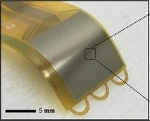
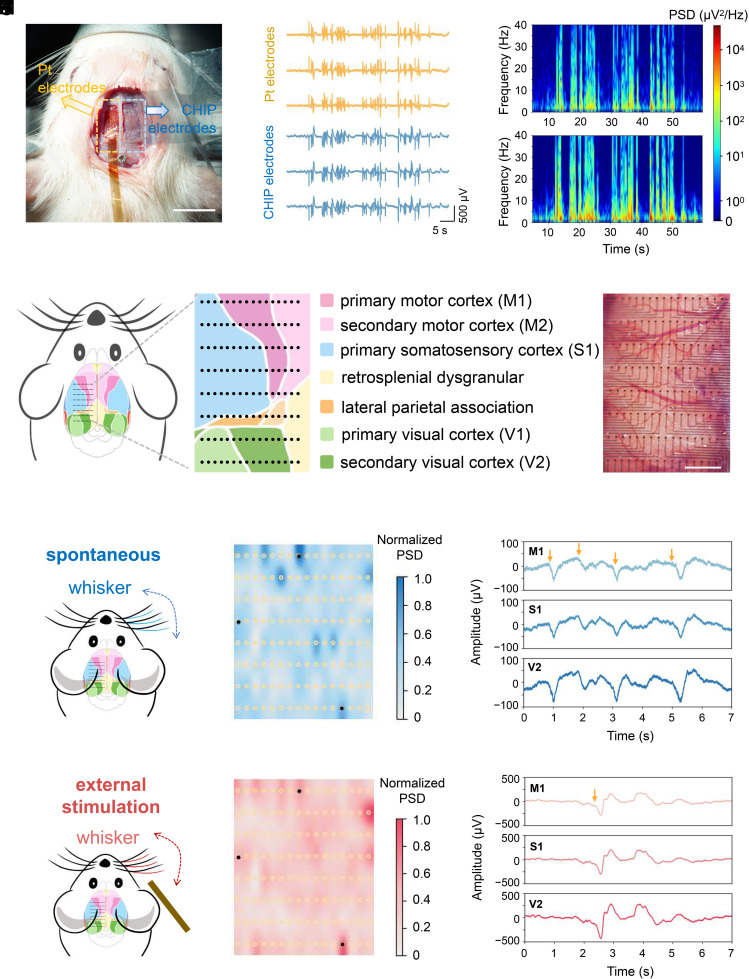
View the interface → Source figure BTSD-ACAD-0095 Figure 4 of the paper: photographs of the CHIP-based array beside a commercial platinum array on rat cortex and of the array covering the cortex (scale bars as published), with recordings, spectrograms, a cortical-area schematic and activity maps in the remaining panels.
Tsinghua SIGS all-organic CHIP hydrogel ECoG array 128-channel ECoG array, 9 micrometers thick, made entirely of a conductive hydrogel (CHIP) printed on parylene, at 853 channels per cm2. Xu Xiaomin's group at Tsinghua Shenzhen International Graduate School with SIAT; rabbit recordings to 550 days (PNAS 2026).
Ecog Preclinical evidence
Photo credit Tsinghua Shenzhen International Graduate School group and collaborators, PNAS (2026), Figure 4 · PNAS · complete Figure 4 · CC BY-NC-ND 4.0 . Complete source image retained byte-for-byte, including every panel and annotation. No cropping, re-encoding, recoloring or synthetic enhancement.
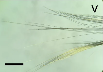
View the interface → Photograph BTSD-ACAD-0060 The independent UFTE electrode fibers spread in distilled water. Scale bar: 1 mm.
Ultra-Flexible Tentacle Electrodes (UFTE) Swiss secondary coverage: 256 contacts on independent polyimide fibers in four bundles. Mechanical loop tethering separates shuttle removal from glue dissolution; the separate 512-channel logger stores data on SD rather than transmitting it.
Intracortical Preclinical evidence
Photo credit Yasar et al., Nature Communications (2024), Fig. 2a(v), CC BY 4.0 · Publisher · original figure · CC BY 4.0 . Select photo 2a(v) and retain 1 mm black scale bar.
Zhiran ultra-100-channel flexible BCI (LEAP trial) Beijing Zhiran's fully implanted wireless intracortical flexible BCI with over 100 channels, in a multicenter registration-style trial (LEAP) that launched at Tiantan Hospital in May 2026. Details come from Chinese hospital and state media releases and company statements.
Intracortical Human evidence
View the interface → Photograph BTSD-ACAD-0064 The long µSEEG electrode with its insertion stylet partly withdrawn, showing the thin flexible body. Scale bar: 1 cm.
µSEEG flexible stylet-guided depth electrode UC San Diego-led 2024 thin-film depth-electrode family: 32/64/128-contact variants, removable stylet, separate PEDOT human and PtNR primate configurations, and polymer/contact failure evidence.
Intracortical Human evidence
Photo credit Lee, Paulk et al., Nature Communications (2024), Fig. 1o, CC BY 4.0 · Publisher · original figure · CC BY 4.0 . Select source photo panel 1o only; preserve full lead, stylet and original scale.