Science biohybrid cortical engraftment implant (microwell / waffle device)
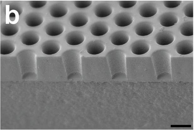
Empty microwell scaffold, sectioned and imaged at 45° tilt. 10 µm scale bar retained.
The demonstrated passive SU-8/fused-silica cortical scaffold from the 2024 mouse study, not the separate electronic biohybrid architecture concept.
Scale: 10 µm bar from the Figure 1b legend, retained in panel.
45°-tilted gold-sputtered SEM; scale measures the image plane. Well depth and pitch should use reported fabrication dimensions.
Image credit & source
Brown et al., Science Corporation (2024 preprint), Fig. 1b · Brown 2024 · Fig. 1b · Copyright reserved; educational reference use requested by site owner.
Source figure image and its PDF soft mask extracted from manuscript page 16, composited on white, panel mechanically cropped; scale retained. No generative changes.
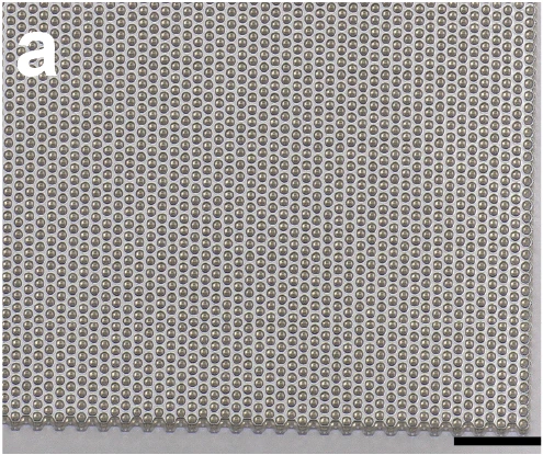
Light micrograph of the scaffold bonded to a coverslip; 100 µm source scale retained.
The demonstrated passive SU-8/fused-silica cortical scaffold from the 2024 mouse study, not the separate electronic biohybrid architecture concept.
Scale: 100 µm source scale bar retained.
Plan-view lattice microscopy. Published scaffold is 5 × 5 mm with 15 µm well pitch; the micrograph shows a local region.
Image credit & source
Brown et al. (2024 preprint), Fig. 1a · Brown 2024 · Fig. 1a · Copyright reserved; educational reference use requested by site owner.
Source figure image and its PDF soft mask extracted from manuscript page 16, composited on white, panel mechanically cropped; scale retained. No generative changes.
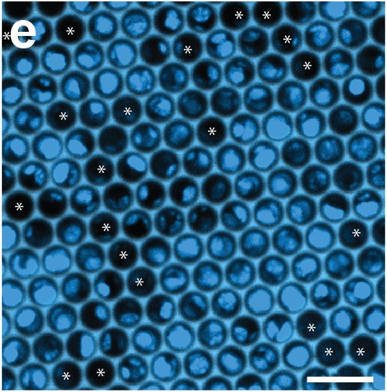
DAPI-stained cell-loaded microwells 24 hours after loading; asterisks mark empty wells. 25 µm source scale retained.
The demonstrated passive SU-8/fused-silica cortical scaffold from the 2024 mouse study, not the separate electronic biohybrid architecture concept.
Scale: 25 µm source scale bar retained.
Confocal image showing loaded cells, not conductive electrode sites.
Image credit & source
Brown et al. (2024 preprint), Fig. 1e · Brown 2024 · Fig. 1e · Copyright reserved; educational reference use requested by site owner.
Source figure image and its PDF soft mask extracted from manuscript page 16, composited on white, panel mechanically cropped; scale retained. No generative changes.
- Code
- ?2R
- Reviewed
- 2026-02-06
- Interface
- ecog
- Evidence stage
- preclinical
Independent, source-linked catalog sheet. Not a manufacturer-issued datasheet, regulatory decision or instructions for clinical use. Human evidence does not establish approval. Source-specific restrictions, conflicts and missing specifications are retained below.
Science biohybrid cortical engraftment implant (microwell / waffle device)
All rows follow the shared implant-device template. Measurements belong to the named study or configuration. A blank cell means the reviewed sources do not establish a value. Proposed architectures, optical behavior and validated electronic recording systems are kept separate.
Identity
| Field | Value and source scope |
|---|---|
| Device | Brown 2024 surface cortical biohybrid microwell scaffold |
| Manufacturer | Science Corporation research fabrication |
| Interface class | Surface cortical cell scaffold with external optical stimulation/readout; not an electrical ECoG array |
| Origin | Brown, Zappitelli, Dawson and Science Corporation team |
| First demonstrated | 2024 preprint reviewed here; no claim of earliest family demonstration |
| First human implant | Mouse preclinical study |
| Species studied | C57/B6J mice, male and female; embryonic primary cortical donor neurons |
| Regulatory status | Animal research under Science Corporation IACUC; reviewed report is a preprint |
| Function | Optogenetically stimulate graft neurons to provide behavioral input; two-photon imaging observes graft activity |
| Target tissue | Cortical surface over S1; graft neurites extend into host cortex |
Geometry and architecture
| Field | Value and source scope |
|---|---|
| Interface type | Cell-loaded surface scaffold bonded to cranial glass window |
| Array layout | Hexagonal microwell lattice, approximately 118000 wells over 25 mm² |
| Electrode count | No electrical recording electrodes reported in this scaffold; wells and neurons are not electrode channels |
| Pitch | 15 µm microwell pitch |
| Electrode lengths | Not applicable to electrode shanks; microwells 15 µm deep |
| Shank width and thickness | No penetrating shanks; 5 x 5 mm scaffold die bonded to 7 mm diameter coverslip |
| Tip and exposed site geometry | Circular well interior 10 µm diameter; walls 2.5 µm thick and 8.6 µm long |
| Contact coating | No electrode coating; scaffold loaded after poly-D-lysine and laminin treatment, 0.1 mg/ml each |
| Insulation | SU-8 microwells on fused silica; passive optical scaffold, not insulated conductive array |
| Insertion method | 5 mm craniotomy plus duratomy; scaffold placed neuron-side-down on cortex |
| Anchoring and fixation | Epotek 301 bonds die to coverslip; Metabond seals coverslip to skull, headplate fixed with Metabond/UV acrylic |
Electrode and channel physics
| Field | Value and source scope |
|---|---|
| Exposed site area | Not applicable to electrical contacts; implanted scaffold area 25 mm² |
| Electrode material | No electrode conductor reported; SU-8/fused silica scaffold and glass coverslip |
| Impedance (with measurement frequency) | Not applicable to passive optical scaffold |
| Noise floor or SNR | Electrical SNR not applicable; numerical optical SNR not reported |
| Recording modality | External two-photon jRGECO1a calcium imaging in three grafted mice, not on-device spike recording |
| Sampling rate | Functional single-plane calcium imaging 30 Hz at 1040 nm |
| Stimulation capability | CheRiff-expressing graft neurons activated by external 470 nm fiber-coupled LED; ten 10 ms pulses at 20 Hz |
| Charge injection limit | Not applicable to optical write; power at ferrule before implant 5 mW, some high-performing animals also tested at 1 mW. Not a validated safety limit |
| Reference and ground | Not applicable to demonstrated optical interface |
Tissue interface and bioresponse
| Field | Value and source scope |
|---|---|
| Target tissue | Graft cell bodies in scaffold; processes grow into superficial cortex and axons observed across cortical layers |
| Insertion trauma and BBB disruption | No electrode shank insertion, but craniotomy, duratomy and residual bleeding requiring Gelfoam. BBB injury not quantitatively measured |
| Vascular disruption risk | Vessels observed in cortical tissue pulled out during terminal scaffold removal; vascular injury rate not reported |
| Micromotion sensitivity | Strong scaffold-brain adhesion at explant; quantitative chronic motion transfer not reported |
| Gliosis and encapsulation | Systematic histology prevented by explant damage; no quantitative gliosis/encapsulation result established |
| Neuron loss near sites | Native-neuron loss not reported. Occupied wells: 77±15% before implantation (n=23), 52±23% fluorescent at three weeks (n=13). Occupancy is not an exact surviving-cell fraction |
| Foreign-body response mitigation | Strain-matched mouse donor/recipient cells used without immunomodulatory therapy in this experiment; does not establish human immune compatibility |
| Typical failure modes | Not all grafted animals learned task (5/9 met criterion); terminal explant routinely fractured scaffold and tore cortex. Quantitative clinical failure rate not established |
System architecture
| Field | Value and source scope |
|---|---|
| Onboard electronics | None reported in the demonstrated microwell scaffold; no integrated microLED or electrode readout |
| Data path | External optical stimulation through cranial window; external two-photon microscope observes fluorescence |
| Telemetry bandwidth | No wireless data telemetry demonstrated; task bit rate is not telemetry bandwidth |
| Sampling rate | External functional imaging 30 Hz; behavioral readout is separate |
| Power | External LED/fiber and microscope; no implanted power supply. Functional imaging approximately 50 mW at 1040 nm, structural imaging 100 mW at 930 nm |
| Thermal management | Temperature rise and phototoxicity limit not reported; optical powers are experimental settings, not safety ratings |
| Packaging and hermeticity | Glass cranial window bonded with epoxy/acrylic/cement; living-cell scaffold, not hermetic electronic package |
| MRI compatibility | |
| Surgical complexity | Craniotomy/duratomy, cell-loaded placement, headplate fixation and later fiber ferrule attachment |
| Output connectors | 400 µm optical cannula, 0.39 NA, Thorlabs CFMLC14L02; external optical fiber and rotary joint, not electrical connector |
Performance envelope
| Field | Value and source scope |
|---|---|
| Acute yield | 77±15% wells occupied at 24 h in 23 loaded scaffolds; mean approximately 90000 cells. Not electrical channel yield |
| Chronic yield | 52±23% wells fluorescent at three weeks in 13 implants; not a long-term channel-survival rate |
| Stability over time | Three-week functional calcium imaging and behavior after three-to-four-week screening. Scaffold visually intact months after implantation, not months of validated BCI function |
| Longevity | Months-scale scaffold integrity observation; maximum functional graft/device lifetime not reported |
| Revision and explant experience | Terminal histology removal frequently tore underlying cortex and fractured scaffold; not a clinical revision series |
| Adverse events | Explant tissue damage documented; no teratomas/overgrowth observed. General safety rate not established |
| Notable demonstrations | 5/9 grafted mice reached behavioral criterion; best-session mean 0.25±0.24 bits/s (n=9), up to 0.7 bits/s. Not per-neuron bandwidth |
Clinical and preclinical evidence
| Field | Value and source scope |
|---|---|
| Human subjects | None in reviewed study |
| Preclinical cohort | Separate counts: 23 loading scaffolds, 13 three-week implants, 3 calcium-imaging mice; behavior 9 biohybrid, 7 positive controls, 4 negative controls, 4 empty/AAV and 4 no-AAV controls. Counts not summed into unique animals |
| Follow-up duration | Three-week survival screen; behavioral screen at three-to-four weeks then three-week training. Months-scale intact scaffold images do not establish long-term functional performance |
| Indications | Preclinical proof of graft-mediated optical input sufficient for goal-directed behavior |
| Trials and registries | Animal IACUC study; no human trial in reviewed source |
| Primary outcomes | Cell loading/occupancy, neurite growth, spontaneous calcium events and optical detection task |
| Key limitations | Preprint; task does not prove chemical synapses as exclusive mechanism; no electrical readout or independent single-neuron channels demonstrated; explant damage limits histology |
Engineering tradeoffs
| Field | Value and source scope |
|---|---|
| Strengths | Dense cell scaffold and optical behavioral input without penetrating electrode shanks |
| Limitations | Cell attrition, incomplete behavioral success, surgical/explant trauma, external optics and unproven human immune compatibility |
| Scaling constraints | Approximately 118000 wells do not mean 118000 communication channels; millions of neurons remain future ambition |
References
- Brown et al. 2024. Optogenetic stimulation of a cortical biohybrid implant guides goal directed behavior. Preprint. Company-hosted full manuscript, Results, Methods and figures.
- Science Corporation architecture description, November 2024. Future electronic architecture is not the same as this passive microwell experiment.