Utah Slanted Electrode Array (USEA)
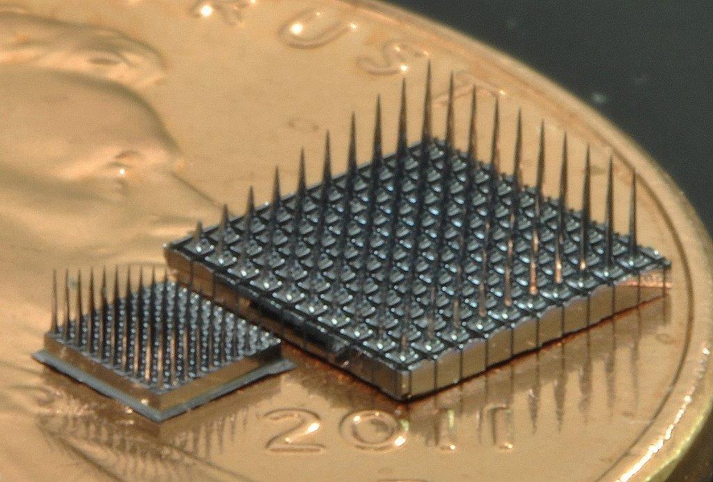
Utah Slant Array manufacturer hardware photograph. Coin is size context, not a calibrated scale bar.
Official current Utah Slant Array page image, showing array samples; not a claim that all samples are the 2017 implanted assembly.
Scale: Coin for context; no calibrated bar.
Perspective product photograph; use reported pitch and shank-length specifications for modeling.
Image credit & source
Utah Slant Array © Blackrock Neurotech · Blackrock Neurotech · Utah Slant Array · Copyright © Blackrock Neurotech; reserved-rights reference.
Source photograph retained intact; no generative changes.
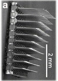
USEA scanning electron micrograph; slanted shank-length profile and 2 mm source scale bar.
Historical slanted array micrograph reproduced in the 2017 human USEA study; not every current Blackrock order option. Third-party SEM copyright remains reserved.
Scale: 2 mm scale bar retained.
Historical USEA architecture image; a tilted electron micrograph does not establish a full three-dimensional coordinate set.
Image credit & source
Wendelken et al. (2017), Fig. 1a; original SEM credited by the authors to Branner et al. (2001). · Wendelken 2017 · Fig. 1a / Branner 2001 · Copyright reserved; educational reference use requested by site owner.
Photographic panel mechanically cropped from the source; resized and encoded as WebP. Source annotations and scale bars retained; no generative changes.
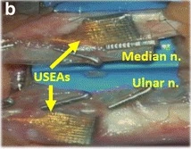
2017 study: USEAs in median and ulnar nerves beneath nerve wraps; labeled surgical close-up.
2017 human study configuration.
Scale: No independent scale bar in this surgical panel.
Placement reference; nerve wrap obscures the individual shank contacts.
Image credit & source
Wendelken et al. (2017), Fig. 1b · Wendelken 2017 · Fig. 1b · CC BY 4.0.
Photographic panel mechanically cropped from the source; resized and encoded as WebP. Source annotations and scale bars retained; no generative changes.
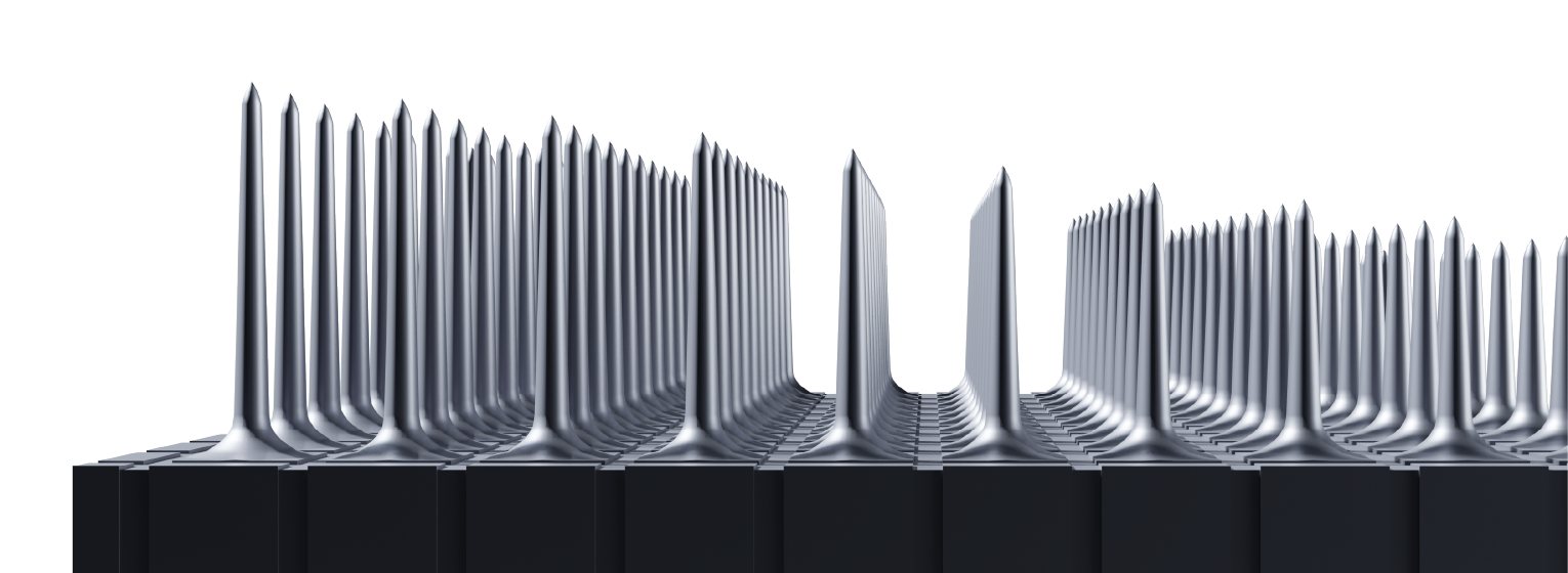
Utah Slant Array manufacturer geometry rendering. Graded penetrating lengths are visible; this is an illustration, not microscopy.
Current Utah Slant Array page illustration.
Scale: No calibrated scale bar.
Manufacturer rendering conveys architecture; it is not an as-built measurement photograph.
Image credit & source
Utah Slant Array © Blackrock Neurotech · Blackrock Neurotech · slant side view · Copyright © Blackrock Neurotech; reserved-rights reference.
Source illustration retained intact; no generative changes.
- Code
- ?3R
- Reviewed
- 2026-10-07
- Interface
- pni
- Evidence stage
- human
Independent, source-linked catalog sheet. Not a manufacturer-issued datasheet, regulatory decision or instructions for clinical use. Human evidence does not establish approval. Source-specific restrictions, conflicts and missing specifications are retained below.
Utah arrays
The slanted array targets different depths in peripheral nerves. It does not supersede the standard cortical Utah array.
Highlighted family sheet: Utah Microelectrode Array (UEA) →
Version history and parallel configurations (2)
- Utah Microelectrode Array (UEA) Standard silicon-array family for cortical recording and stimulation.
- Utah Slanted Electrode Array (USEA) Unequal shank lengths sample nerve fascicles at different depths.
Utah Slanted Electrode Array (USEA)
A penetrating silicon array with unequal electrode lengths for peripheral-nerve recording and stimulation. This sheet separates current manufacturer options from the particular arrays implanted in the 2017 human study. A physical needle, a connected channel and a usable recording channel are not the same count.
Core interface specifications
The 12 fields follow the Blackrock Utah table for comparison, not a manufacturer-issued datasheet. Missing values stay blank; inapplicable fields are marked. Configuration-specific details and limits follow below.
| Field | Specification and source scope |
|---|---|
| Electrode Pitch | 400 µm, 2017 study and current manufacturer |
| Channel Count | 2017: 100 physical needles, 96 recording/stimulation paths plus four on-array reference electrodes. Current options: 16-96; 1024 wording is multi-configuration system scope |
| Output Connectors | 2017: custom PCB with ZIF-Clip-96. Current manufacturer: Omnetics, CerePort pedestal 128/256, Custom |
| Output Conn. dimensions L x W x H | Current page: Omnetics 7 × 37 × 9 mm; CerePort 128 16.5 × 12 × 19 mm, 256 16.5 × 10.7 × 19 mm (height × neck diameter × base diameter). Not the 2017 PCB dimensions; those are not reported here |
| Standard Electrode Lengths | 2017 approximately 0.75-1.5 mm. Current table custom 0.75-1.5 mm; overview has 0.5-1.5 mm grading |
| Impedance | Current manufacturer: platinum 20-800 kΩ; SIROF/IrOx 1-80 kΩ, frequency not stated. Study checks at 1 kHz; ≥500 kΩ is that analysis’s failed-channel threshold |
| Array Dimensions | 2017: 10 × 10 needles on a 4 × 4 mm base. Current table: “Customizable from 2 - 12”, no unit printed |
| Multi-Port Options | Current options: 1, 2, 3, 4. Not a claim of the 2017 study assembly |
| Metalization | Current platinum or sputtered iridium oxide (SIROF); no generic coating assigned to the particular 2017 study from options alone |
| Wire Bundle Length | Current customizable 20-130 mm; specific 2017 lead length not reported here |
| Reference and Ground | 2017: four on-array corner references plus two looped platinum wires as off-array reference and ground. Current page: “Ground Source and Selectable Reference Wires” |
| Insulation | Current manufacturer: Parylene-C; study-specific coating stack not extracted here |
Identity
| Field | Value and source scope |
|---|---|
| Device | Utah Slant / USEA silicon-array family [1]; published human configuration is the 2017 median/ulnar-nerve research arrays, not every current order option [2] |
| Manufacturer | Blackrock Neurotech; the 2017 paper names Blackrock Microsystems [1, 2] |
| Interface class | Intrafascicular peripheral nerve, penetrating silicon array |
| Origin | |
| First demonstrated | |
| First human implant | The 2017 human study is the published configuration used here [2]; first-implant year not supplied by this sheet |
| Species studied | Human (two subjects in the 2017 study) [2]; manufacturer also reports primate experience [1] |
| Regulatory status | Manufacturer describes human research under IDE; investigational, not general commercial approval [1] |
| Function | Recording and electrical stimulation [1, 2] |
| Target tissue | Peripheral nerve (median and ulnar nerves in the 2017 study) [2] |
Geometry and architecture
| Field | Value and source scope |
|---|---|
| Interface type | Penetrating intrafascicular slanted array |
| Array layout | 2017: 10 x 10 grid of 100 needles on a 4 x 4 mm base [2] |
| Electrode count | 2017: 100 physical needles, 96 recording/stimulation paths, four corner references [2]. Current options: 16-96 channels; the 1,024 wording is multi-configuration system scope [1] |
| Pitch | 400 µm, 2017 study and current manufacturer [1, 2] |
| Electrode lengths | 2017: approximately 0.75-1.5 mm [2]. Current table: custom 0.75-1.5 mm; overview: 0.5-1.5 mm linear grading [1] |
| Shank width and thickness | |
| Tip and exposed site geometry | Sharpened silicon; exact exposure not specified |
| Contact coating | Current options: platinum or sputtered iridium oxide (SIROF); no coating assigned to the 2017 arrays from options alone [1] |
| Insulation | Current manufacturer: Parylene-C; study-specific coating stack not extracted here [1] |
| Insertion method | Pneumatic impactor after epineurium dissection, 2017 Methods [2] |
| Anchoring and fixation | Wire bundle, ground and reference wires sutured to epineurium; collagen wrap secured with vascular clips, 2017 Methods [2] |
Electrode and channel physics
| Field | Value and source scope |
|---|---|
| Exposed site area | Older generic figures were removed |
| Electrode material | Silicon needles with platinum or SIROF contact metallization [1] |
| Impedance (with measurement frequency) | Manufacturer: platinum 20-800 kΩ, SIROF/IrOx 1-80 kΩ, frequency not stated [1]. Study check at 1 kHz; 500 kΩ or more classified as failed for that analysis, not a universal threshold [2] |
| Noise floor or SNR | System dependent; no array-level noise specification |
| Recording modality | Intrafascicular peripheral-nerve recording; single-fiber and multi-unit selectivity claims are study-specific [2] |
| Sampling rate | Set by the external recording/stimulation system; configuration dependent |
| Stimulation capability | Yes; the 2017 study used biphasic stimulation; waveform limits not inferred here [2] |
| Charge injection limit | No universal material charge limit assigned; requires configuration-specific instructions and evidence |
| Reference and ground | 2017: four on-array corner references plus two looped platinum wires as off-array reference and ground [2]. Current page: ground source and selectable reference wires [1] |
Tissue interface and bioresponse
| Field | Value and source scope |
|---|---|
| Target tissue | Peripheral nerve fascicles [2] |
| Insertion trauma and BBB disruption | Insertion trauma is a qualitative concern of rigid needles; no quantitative value |
| Vascular disruption risk | |
| Micromotion sensitivity | Mechanical fragility under lead forces noted qualitatively; no quantitative data |
| Gliosis and encapsulation | Fibrosis around rigid silicon needles noted qualitatively; no quantitative data |
| Neuron loss near sites | |
| Foreign-body response mitigation | |
| Typical failure modes | Different channel-loss trends across arrays in the 2017 four- and five-week windows [2] |
System architecture
| Field | Value and source scope |
|---|---|
| Onboard electronics | None on the array; passive electrodes routed through percutaneous wires |
| Data path | Percutaneous wires to a custom PCB and ZIF-Clip-96 connection, 2017 study [2] |
| Telemetry bandwidth | Not applicable; wired |
| Sampling rate | Set by the external recording/stimulation system; configuration dependent |
| Power | External recording/stimulation hardware, not an autonomous wireless implant |
| Thermal management | External |
| Packaging and hermeticity | Percutaneous research assembly, not a hermetic implant |
| MRI compatibility | Not established; no compatibility assertion |
| Surgical complexity | Microsurgery with nerve dissection and pneumatic impact insertion, 2017 Methods [2] |
| Output connectors | 2017: custom PCB with ZIF-Clip-96 [2]. Current: Omnetics, CerePort pedestal 128/256, custom [1] |
Performance envelope
| Field | Value and source scope |
|---|---|
| Acute yield | 96 recording/stimulation paths per implanted array in the 2017 configuration [2] |
| Chronic yield | Working channels tracked over the implants, with different channel-loss trends across arrays in the two subjects [2] |
| Stability over time | Four-week (S3) and five-week (S4) windows in the 2017 study; no standard multi-year lifetime established [2] |
| Longevity | Manufacturer reports more than ten years of recording in primates and six years in humans across its broader experience; not the follow-up of the 2017 cohort [1] |
| Revision and explant experience | |
| Adverse events | No observed long-term functional deficits reported in the 2017 window; long-term safety not established by it [2] |
| Notable demonstrations | Virtual-hand control and evoked proprioceptive and cutaneous sensations, 2017 human study [2] |
Clinical and preclinical evidence
| Field | Value and source scope |
|---|---|
| Human subjects | Two subjects, each with a median-nerve and an ulnar-nerve array [2] |
| Preclinical cohort | Manufacturer cites primate experience [1]; cohort not detailed |
| Follow-up duration | Four weeks (S3) and five weeks (S4) [2] |
| Indications | Investigational: sensorimotor prosthetic control and sensory feedback research [1, 2] |
| Trials and registries | Manufacturer notes IDE/IRB support is needed for human use [1]; no registry identifier pinned in this sheet |
| Primary outcomes | Virtual-hand control and evoked sensations; the abstract’s up-to-131 percepts belong to the study, not a per-implant guarantee [2] |
| Key limitations | Short implanted window; the abstract’s 100-channel wording versus 96 allocated electrodes and four references; different count scopes are not merged [2] |
Engineering tradeoffs
| Field | Value and source scope |
|---|---|
| Strengths | Very high intrafascicular selectivity, bidirectional recording and stimulation, demonstrated human motor decoding and sensory feedback |
| Limitations | Insertion trauma, micromotion and fibrosis around rigid silicon needles, percutaneous connector burden, mechanical fragility under lead forces |
| Scaling constraints | Per-channel wiring and connector complexity, nerve geometry limits on array placement, chronic tissue response |
2017 study hardware and current manufacturer options
| Property | 2017 study hardware | Current manufacturer page |
|---|---|---|
| Physical electrodes | 100 in a 10 × 10 grid | Overview says 100 electrodes |
| Recording/stimulation paths | 96; four corner electrodes used as references | Specification table: 16-96 channels; overview also advertises up to 1,024 channels across multiple configurations |
| Base | 4 × 4 mm | Customizable; no single footprint substituted here |
| Pitch | 400 µm | 400 µm |
| Electrode length | Approximately 0.75-1.5 mm | Overview: 0.5-1.5 mm linear grading; specification table: custom 0.75-1.5 mm |
| Contact coatings | Do not infer one coating from generic Utah-family figures | Platinum or sputtered iridium oxide (SIROF/IrOx) |
| Insulation | Study-specific fabrication details not extracted here | Parylene-C |
| Insertion method | Pneumatic impactor after epineurium dissection, 2017 study Methods | Configuration-dependent tooling; specifics not reported |
| Anchoring / fixation | Wire bundle, ground and reference wires sutured to epineurium; collagen wrap secured with vascular clips, 2017 study Methods | Not reported |
The abstract calls the arrays “100-channel”; Methods explicitly allocates 96 electrodes for recording/stimulation and four for on-array reference. Both descriptions are preserved. The manufacturer’s 100-needle overview, 16-96-channel table and up-to-1,024-channel system wording are different scopes, not one 1,024-site implant. Electrode area, exposed tip dimensions and one universal noise floor are not established by the sources inspected here.
Electrode and channel conditions
| Property | Specification and condition |
|---|---|
| Platinum impedance | Manufacturer: 20-800 kΩ; measurement frequency not stated on this page |
| SIROF/IrOx impedance | Manufacturer: 1-80 kΩ; frequency not stated on this page |
| Study impedance check | 1 kHz; electrodes at or above 500 kΩ were classified as failed for this analysis |
| Study connection | Percutaneous wires to a custom PCB and ZIF-Clip-96 recording/stimulation connection |
| Current connector options | Omnetics, CerePort 128/256 and custom, per manufacturer |
| Current lead options | Manufacturer: 20-130 mm wire bundle |
| Power and acquisition | External recording/stimulation hardware, not an autonomous wireless implant |
| Exposed site area | Older generic ~200-400 µm² figures were removed |
| Noise floor / SNR | System-dependent; no array-level noise specification |
| Recording modality | Intrafascicular peripheral-nerve recording; single-fiber and multi-unit selectivity claims are study-specific |
| Stimulation capability | Yes; 2017 study used biphasic stimulation; configuration-specific waveform limits not inferred here |
| Charge injection limit | No universal material charge limit assigned; requires configuration-specific instructions and evidence |
| Tip geometry | Sharpened silicon; exact exposure not specified |
| MRI labeling | Not established here; no compatibility assertion |
A study’s failure threshold is not the manufacturer’s acceptable impedance range or a universal clinical safety threshold. Connector model names do not determine electrode count. Safe charge limits, waveform limits and tissue-current density require configuration-specific instructions and evidence; none is inferred from the generic array name.
Tissue response notes
Nerve penetration, lead motion and the percutaneous connection are separate engineering concerns. The 2017 study tracked working channels during four/five-week implants and found different channel-loss trends across arrays. These bounded observations do not establish a standard multi-year lifetime.
The current manufacturer reports more than ten years of recording in primates and six years in humans. Those are manufacturer claims about its broader experience, not the follow-up of the two-subject 2017 paper. This sheet does not convert them into a warranty or independently audited cohort result.
Study narrative
Two subjects each received two arrays, one in the median nerve and one in the ulnar nerve. Implant duration was four weeks for S3 and five weeks for S4. The study demonstrated virtual-hand control and evoked proprioceptive/cutaneous sensations, with a one-degree-of-freedom closed-loop task in one subject. Up to 12 degrees of freedom in informal freeform decoding, five independent real-time degrees of freedom and four proportional degrees of freedom describe different tasks.
The paper reports no observed long-term functional deficits from the implants, but the short implanted observation window does not establish long-term electrical reliability or general safety. Its abstract’s up-to-131 percepts belong to the study, not a specification guaranteeing 131 percepts per implant.
The manufacturer’s IDE wording describes investigational human use and says teams need IDE/IRB support. No general clearance for arbitrary implantation is inferred. First-implant year, patient-wide lifetime statistics and one universal tissue-risk grade are not supplied by this sheet.
Model limits
The site’s 100-needle reference geometry is not a reconstruction of every current USEA option or the complete 2017 assembly. Exact exposed contacts, wire routing, insulation geometry and connector packaging remain outside that model. Unknown dimensions, charge limits and MRI conditions remain unknown rather than being filled with generic Utah-array numbers.
References
- Blackrock Neurotech. Utah Slant Array, current manufacturer specification and research-use descriptions, checked 7 October 2026.
- Wendelken S et al. 2017 human study, full primary Methods and results.
- Same primary manuscript in PMC.
- Primary indexed abstract.
- George JA et al. 2020 decoding study cited in the earlier sheet. Its different protocol is not used to fill the 2017 hardware configuration.
Models and reference visualizations
Utah Slanted Array · 0.5–1.5 mm
Electrode-bearing structure · dimensions in millimeters
Loading 3D viewer…
Model fidelity. Uses the manufacturer’s 0.5–1.5 mm feature description; its specification table separately lists custom 0.75–1.5 mm lengths. The exact ten-column progression is an idealization. Substrate dimensions follow the Utah family; maximum shaft radius, smoothly tapering profile with basal flare, and the highlighted tip region are illustrative. The profile follows the source silhouette, not a measured fabrication profile. Leads and connector are omitted.
Color, transparency and surface finish approximate the references. Use Highlight contacts to inspect electrode locations.
Sources & reference images
Dimensions come from the linked specifications; images guide shape only. Reference images remain on their owners’ websites.
- Blackrock — Slant Array specifications and side view →
- Blackrock — Utah Array specifications and photographs →
- Manufacturer slanted-array side-view rendering →
JSON includes physical site coordinates, unknown channel mappings and approximation notes. GLB uses meters. These models do not predict recording or stimulation performance.