Utah Microelectrode Array (UEA)
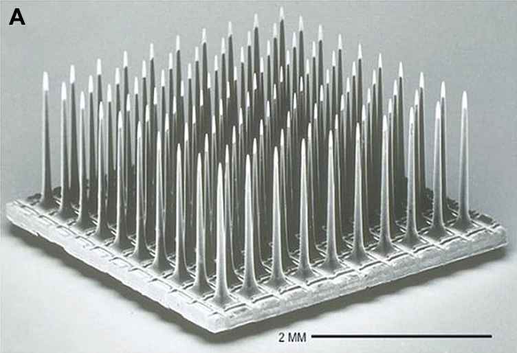
Utah electrode array, scanning electron micrograph. 2 mm scale retained.
Unwired 100-electrode research array (2014), not the complete current NeuroPort assembly.
Image credit & source
Fernandez et al., Frontiers in Neuroengineering (2014), Fig. 1A · Frontiers · Figure 1A · CC BY 3.0.
Photographic panel cropped from the original figure; resized and re-encoded. Original scale bars and annotations retained.
- Code
- C3?
- Reviewed
- 2026-10-07
- Interface
- intracortical
- Evidence stage
- human
Independent, source-linked catalog sheet. Not a manufacturer-issued datasheet, regulatory decision or instructions for clinical use. Human evidence does not establish approval. Source-specific restrictions, conflicts and missing specifications are retained below.
Utah arrays
The slanted array targets different depths in peripheral nerves. It does not supersede the standard cortical Utah array.
Version history and parallel configurations (2)
- Utah Microelectrode Array (UEA) Standard silicon-array family for cortical recording and stimulation.
- Utah Slanted Electrode Array (USEA) Unequal shank lengths sample nerve fascicles at different depths.
Utah Microelectrode Array (UEA)
A silicon array of penetrating electrodes for recording cortical neural activity. The Utah research family and the NeuroPort clinical product share an array architecture, but their configurations, labeling and permitted uses are not interchangeable.
Primary manufacturer: Blackrock Neurotech. The University of Utah is the array’s origin; the BrainGate consortium is a clinical research user. These are different roles, rather than three interchangeable manufacturers.
The BrainGate pilot used a 96-microelectrode sensor for a human neural cursor and device control.
Core interface specifications
The 12 fields follow the Blackrock Utah table for comparison, not a manufacturer-issued datasheet. Missing values stay blank; inapplicable fields are marked. Configuration-specific details and limits follow below.
| Field | Specification and source scope |
|---|---|
| Electrode Pitch | 400 µm; current Utah manufacturer page |
| Channel Count | 16-1024 in the current system/options table; not one array. Overview says up to 96 per array, FAQ 96-128. NeuroPort IFU: 100 physical, 96 connected |
| Output Connectors | Utah options: Omnetics, CerePort pedestal 128/256, Custom |
| Output Conn. dimensions L x W x H | Utah page: Omnetics 7 × 37 × 9 mm; CerePort 128 16.5 × 12 × 19 mm and 256 16.5 × 10.7 × 19 mm (height × neck diameter × base diameter). Research IFU instead gives Omnetics 9 mm height, 7 mm base length, 13 mm base width; conflict retained |
| Standard Electrode Lengths | Utah: 0.5-1.5 mm research; 1.0-1.5 mm clinical. NeuroPort configuration: 1.0 or 1.5 mm |
| Impedance | Utah page: platinum 20-800 kΩ; SIROF/IrOx 1-80 kΩ; frequency not stated. NeuroPort values and IFU differences retained below |
| Array Dimensions | Utah table literally says “Customizable from 2 - 12” with no unit. FAQ: 4 × 4 mm footprint, 0.2 mm substrate; not a universal customized layout |
| Multi-Port Options | 1, 2, 3, 4, Utah options table; not equivalent to the electrode count |
| Metalization | Platinum or sputtered iridium oxide (SIROF). Utah page repeats impedance ranges in this row; those are not material dimensions |
| Wire Bundle Length | Utah options: customizable 20-130 mm. NeuroPort page: 13 cm long, 0.55 mm wide |
| Reference and Ground | Utah page: “Ground Source and Selectable Reference Wires”. Assembly pin mapping is configuration-specific, not inferred from a connector name |
| Insulation | Parylene-C, Utah options table; not a lifetime or MR-safety qualification |
Identity
| Field | Value and source scope |
|---|---|
| Device | Utah Microelectrode Array research family; NeuroPort is the human clinical configuration |
| Manufacturer | Blackrock Neurotech (formerly Blackrock Microsystems) |
| Interface class | Intracortical, penetrating silicon microelectrode array |
| Origin | University of Utah |
| First demonstrated | Not restated without a cited source; the origins entry covers early manufacturing history |
| First human implant | Earlier unsourced dates were removed rather than kept |
| Species studied | Human (NeuroPort programs) and non-human primate (2013 Barrese cohort) |
| Regulatory status | NeuroPort April 2022 IFU: temporary recording and monitoring for less than 30 days; research arrays are investigational |
| Function | Recording; the research page also describes stimulation. The NeuroPort labeling conflict is kept below |
| Target tissue | Cerebral cortex |
Geometry and architecture
| Field | Value and source scope |
|---|---|
| Interface type | Penetrating intracortical array |
| Array layout | NeuroPort: 10 x 10 grid; research family configurable |
| Electrode count | 100 physical, 96 connected (NeuroPort IFU); conflicting manufacturer marketing counts are preserved in Published geometry |
| Pitch | 400 µm, current Utah and NeuroPort pages |
| Electrode lengths | 0.5-1.5 mm research; 1.0-1.5 mm clinical |
| Shank width / thickness | Utah FAQ gives a 4 x 4 mm footprint, 0.2 mm substrate |
| Tip and exposed site geometry | Not reconstructed |
| Contact coating | Platinum or sputtered iridium oxide (SIROF) |
| Insulation | Parylene-C, Utah options table |
| Insertion method | Configuration-dependent tooling; specifics not reported |
| Anchoring and fixation | Percutaneous pedestal or connector; array fixation detail not reported |
Electrode and channel physics
| Field | Value and source scope |
|---|---|
| Exposed site area | |
| Electrode material | Silicon shank with platinum or SIROF contact metallization |
| Impedance (with measurement frequency) | NeuroPort page: platinum 100-800 kΩ, SIROF at most 50 kΩ at 1 kHz; Utah table: platinum 20-800 kΩ, SIROF/IrOx 1-80 kΩ with frequency unstated; 2022 IFU: 100-800 kΩ platinum, 1-80 kΩ iridium oxide. Source-specific figures kept, not merged |
| Noise floor | Acquisition-system dependent |
| Recording modality | Single- and multi-unit spiking and local field potentials in published use |
| Sampling rate | Configuration dependent; set by the external acquisition system |
| Stimulation capability | Research arrays: described by the manufacturer. NeuroPort IFU: recording-only labeling; conflict retained in Recording and stimulation |
| Charge injection limit | |
| Reference and ground | ”Ground Source and Selectable Reference Wires”, Utah page |
Tissue interface and bioresponse
| Field | Value and source scope |
|---|---|
| Target tissue | Cerebral cortex |
| Insertion trauma / BBB disruption | Inherent to penetrating insertion; no quantitative value |
| Vascular disruption risk | Qualitative risk of penetrating placement; not reported quantitatively |
| Micromotion sensitivity | Rigid silicon array in soft tissue; qualitative concern, no reviewed quantitative source |
| Gliosis and encapsulation | Meningeal reactions and insulation degradation documented in the 2013 macaque failure cohort |
| Neuron loss near sites | |
| Foreign-body response mitigation | |
| Typical failure modes | Connector failures, meningeal reactions, insulation degradation and gradual channel loss in the 2013 cohort |
System architecture
| Field | Value and source scope |
|---|---|
| Onboard electronics | None on the array; passive electrodes routed to a percutaneous connector |
| Data path | Wired percutaneous connection to external acquisition hardware |
| Telemetry bandwidth | Not applicable; wired |
| Sampling rate | Configuration dependent |
| Power | External |
| Thermal management | External |
| Packaging and hermeticity | Not a hermetically sealed implant; percutaneous connector |
| MRI compatibility | |
| Surgical complexity | Craniotomy, array insertion and percutaneous pedestal placement |
| Output connectors | Omnetics, CerePort pedestal 128/256, custom (Utah options) |
Performance envelope
| Field | Value and source scope |
|---|---|
| Acute yield | Not given as a single figure |
| Chronic yield | 2013 macaque cohort: recording durations 0-2,104 days, median 182 days; 62 of 78 arrays failed completely |
| Stability over time | Variable across the cohort; see Long-term evidence and failures |
| Longevity | Manufacturer claims more than eight years in one patient; a single-patient marketing claim, not a cohort result |
| Revision and explant experience | |
| Adverse events | Percutaneous infection risk is noted qualitatively; no rate |
| Notable demonstrations | BrainGate human cursor and device control (BrainGate pilot) |
Clinical and preclinical evidence
| Field | Value and source scope |
|---|---|
| Human subjects | Documented in the BrainGate pilot and subsequent programs; a single audited participant count is not pinned here |
| Preclinical cohort | 78 arrays in 27 rhesus macaques, 2013 failure analysis |
| Follow-up duration | Up to 2,104 days in the macaque cohort; human durations vary by program |
| Indications | Research use for paralysis and motor impairment |
| Trials and registries | BrainGate pilot entry; registry identifiers not pinned in this sheet |
| Primary outcomes | Cursor, communication and device control in published studies |
| Key limitations | Heterogeneous configurations, variable chronic performance, and manufacturer-versus-study figure conflicts that are preserved rather than merged |
Engineering tradeoffs
| Aspect | Assessment |
|---|---|
| Strengths | Decades of research use, direct cortical access, demonstrated chronic human recording, configurable research family |
| Limitations | Rigid penetrating silicon, percutaneous connector burden, chronic signal loss, configuration and labeling inconsistencies |
| Scaling constraints | Per-channel wiring and connector complexity, chronic tissue response, surgical placement time |
Published geometry
| Field | Source and configuration |
|---|---|
| Electrode pitch | 400 µm, current Utah and NeuroPort product pages |
| Utah research lengths | 0.5 to 1.5 mm, current product page |
| NeuroPort lengths | 1.0 or 1.5 mm, current product page and April 2022 IFU |
| NeuroPort layout | 10 x 10, current product page |
| NeuroPort electrode count | 100 physical electrodes, 96 connected to the percutaneous connector, April 2022 IFU |
| Utah substrate | 4 x 4 mm footprint and 0.2 mm thickness, current Utah FAQ |
| Tip coatings | Platinum or sputtered iridium oxide film (SIROF), current product pages |
| NeuroPort wire bundle | 13 cm long, 0.55 mm wide, current product page |
The manufacturer does not give one consistent electrode count for the whole Utah family. Its current overview says “up to 96 electrodes per array”; the FAQ says “up to 128”, “100 - 128” microneedles and “96 - 128” electrodes. Those figures are preserved rather than treated as the same configuration. Connector names such as CerePort 128 do not, by themselves, establish the number of connected recording sites.
The 1991 manufacturing geometry describes a 4.2 mm substrate. That is historical geometry, not a replacement for the current manufacturer’s 4 mm FAQ figure.
Recording and stimulation
The Utah research page describes recording and stimulation. NeuroPort labeling needs its own distinction: the April 2022 NeuroPort Electrode IFU lists temporary recording and monitoring for less than 30 days, and says this recording device should not be used in applications involving stimulation. The current NeuroPort marketing page describes recording and stimulation. This entry does not erase that conflict or treat a marketing page as clinical authorization. Long-term research use and individual clinical protocols are separate from the IFU’s labeled use.
The NeuroPort product page lists platinum impedance of 100 to 800 kΩ and SIROF impedance of at most 50 kΩ at 1 kHz. The 2022 IFU lists 100 to 800 kΩ for its platinum configurations and 1 to 80 kΩ for its iridium-oxide configurations. These are source- and configuration-specific figures, not one generic Utah impedance range.
Long-term evidence and failures
The 2013 retrospective failure study followed 78 arrays in 27 rhesus macaques. Recording duration ranged from 0 to 2,104 days, with a median of 182 days across all arrays. Sixty-two failed completely; nine experiments ended electively and seven were still active at study close. Connector failures, meningeal reactions and insulation degradation were important findings. These are cohort results, not a service-life warranty or a direct estimate of modern human implant survival.
The current NeuroPort page claims recording and stimulation for more than eight years in one patient. That manufacturer claim is not the same evidence as the historical macaque cohort. The older study’s approximately eight-year complete-signal-loss estimate was a prediction from trends, not an observed eight-year survival result.
Model limits
The site’s Utah model is a reference array geometry, not a reconstruction of every sold configuration or a clinical implant assembly. The sources above do not specify a complete current shank profile, tip exposure geometry or every packaging component. No new geometry is inferred here.
Sources
-
Blackrock Neurotech. Utah Array, current product page. Read 7 October 2026.
-
Blackrock Neurotech. NeuroPort Electrode 96, current product page. Read 7 October 2026.
-
Blackrock Microsystems. NeuroPort Electrode IFU, revision 3.00, April 2022.
-
Barrese JC et al. Failure mode analysis of silicon-based intracortical microelectrode arrays in non-human primates. Journal of Neural Engineering, 2013.
-
Blackrock Microsystems. Research Arrays IFU, LB-0514 revision 5.00, November 2020; connector dimensions differ from the current web table.
Models and reference visualizations
Utah Array · 10 × 10 · 1.5 mm
Electrode-bearing structure · dimensions in millimeters
Loading 3D viewer…
Model fidelity. Published pitch, footprint, substrate thickness and selected shank length. Maximum shaft radius (40 µm), the smoothly tapering profile with basal flare, and the 80 µm tip region are illustrative, not measured contact area. The taper follows the source silhouette without claiming a recovered fabrication profile. All 100 physical shanks are shown; no acquisition channel map is inferred. Leads and connector are omitted.
Color, transparency and surface finish approximate the references. Use Highlight contacts to inspect electrode locations.
Sources & reference images
Dimensions come from the linked specifications; images guide shape only. Reference images remain on their owners’ websites.
- Blackrock — Utah Array specifications and photographs →
- Manufacturer Utah tissue-facing tips →
- Manufacturer 10 × 10 array backside photograph →
JSON includes physical site coordinates, unknown channel mappings and approximation notes. GLB uses meters. These models do not predict recording or stimulation performance.
From an array to a real signal
Explore attempted handwriting recorded from two 96-channel Utah arrays in participant T5's motor cortex. These are measured recordings, not simulated signals.
Loading the recording excerpts...
Source, license & limitations
Willett, F. R., Avansino, D. T., Hochberg, L. R., Henderson, J. M. & Shenoy, K. V. (2021). High-performance brain-to-text communication via handwriting. BrainGate2 study participant T5.
Dryad dataset · doi:10.5061/dryad.wh70rxwmv · CC0 public-domain dedication and archive mirror. Three excerpts from the December 18, 2019 session; original 10 ms counts retained without invented spike timing. Only the rate trace is averaged.
Threshold crossings were detected at −3.5×RMS, per the dataset documentation. These files do not contain raw voltage or exact spike timestamps. The page does not run a decoder, reconstruct handwriting, or claim these samples represent all implants or participants. Channel order follows the dataset, not the 3D model's physical contact mapping.
Watch letters emerge from the signal
A decoder trained on four of T5's calibration sessions scores every 20 ms slice of these held-out recordings against 31 characters. Pick a moment to inspect its top five guesses.
Loading the decoder...
Applications
- BrainGate pilot, first human results (2006)
- Handwriting BCI (Willett, 2021)
- Bidirectional BCI with tactile feedback (Flesher, 2021)
- Intracortical typing BCI (Pandarinath, 2017)
- 7 degree-of-freedom neuroprosthetic arm (Collinger, 2013)
- Utah array failure analysis, Barrese 2013
- Zhejiang University: first Chinese human Utah-array implant, robotic arm control, 2020
- Zhejiang University: Chinese handwriting trajectory decoding from motor cortex, 2025
- UC Davis intracortical speech neuroprosthesis in ALS, 2024
- Intracortical auditory-feedback speller in completely locked-in ALS, 2022
- Case Western iBCI-controlled FES for reaching and grasping, 2017
- Patterned ICMS for tactile edges and motion in human somatosensory cortex, 2025
- BCI study of neural constraints on learning in macaque motor cortex, 2014