Devices

Catalog specification sheet - Intracortical

Neurotrophic Electrode (Kennedy cone electrode)

Physical interfaceOptical micrograph
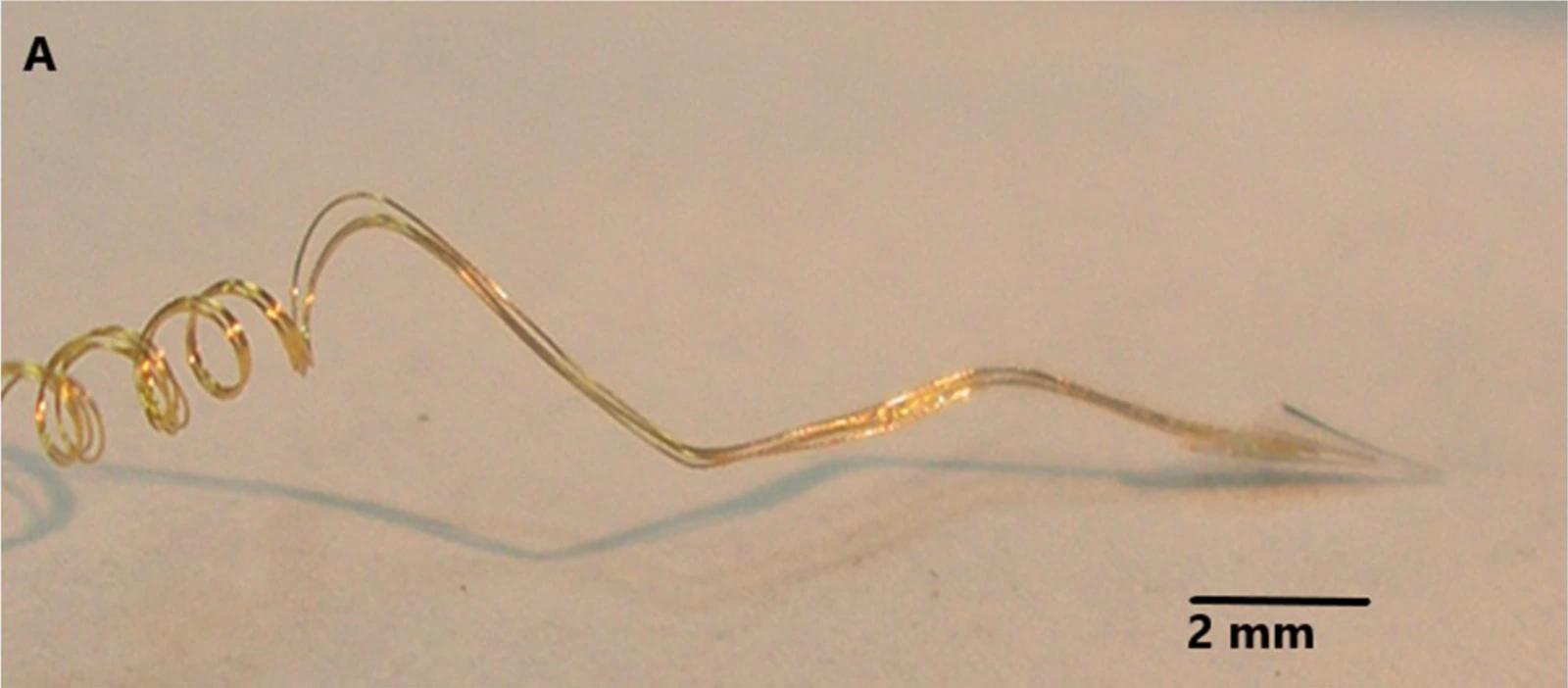
Microscope photograph of fine coiled gold electrode wires entering a small glass cone at the tip of a neurotrophic electrode.

Neurotrophic cone-electrode assembly photographed under magnification; 2 mm scale retained.

Example assembly from the cited 2020 paper; experimental wire configurations differ.

Image credit & source

Gearing and Kennedy, Frontiers in Human Neuroscience (2020), Fig. 1A · Frontiers · Figure 1A · CC BY 4.0.

Photographic panel cropped from the original figure; resized and re-encoded. Original scale bars and annotations retained.

Optical micrograph

Neurotrophic Electrode (Kennedy cone electrode)

Microscope photograph of fine coiled gold electrode wires entering a small glass cone at the tip of a neurotrophic electrode.

Open full-resolution image (1600 × 702) →

Neurotrophic cone-electrode assembly photographed under magnification; 2 mm scale retained.

Gearing and Kennedy, Frontiers in Human Neuroscience (2020), Fig. 1A · Source · CC BY 4.0 · Photographic panel cropped from the original figure; resized and re-encoded. Original scale bars and annotations retained.

Code
?3R
Reviewed
2026-02-06
Interface
intracortical
Evidence stage
human

Independent, source-linked catalog sheet. Not a manufacturer-issued datasheet, regulatory decision or instructions for clinical use. Human evidence does not establish approval. Source-specific restrictions, conflicts and missing specifications are retained below.

Neurotrophic Electrode (Kennedy cone electrode)

The tables use the same field framework as the other implant-device sheets. Values belong to the named study or configuration. A blank cell means the reviewed sources do not establish a value, not that the device lacks that property.

Identity

FieldValue and source scope
DeviceNeurotrophic electrode, Kennedy cone family
ManufacturerNeural Signals research program; 2008 assembly report
Interface classIntracortical neurite-ingrowth electrode
OriginKennedy and collaborators; historical human recording program
First demonstrated
First human implantA human restoration report was published in 1998; earliest implantation date not established by this audit
Species studiedHuman in reviewed 2008 and 2020 reports
Regulatory status2020 study reports FDA IDE G960032; not general commercial approval
FunctionRecording for communication research
Target tissueMotor speech cortex in the reviewed subject

Geometry and architecture

FieldValue and source scope
Interface typePenetrating intracortical glass cone with ingrown neuropil
Array layoutHollow glass cone containing gold wires
Electrode countThree gold wires and two recording channels in 2020 subject 5; 2008 abstract describes a four-wire version, not one universal count
PitchConfiguration dependent; wires offset inside cone, no uniform grid pitch
Electrode lengthsCone length 1.5-2 mm, 2020 Methods
Shank width and thicknessCone openings: 50 µm at deep end and 200-300 µm at upper end, 2020 Methods; wall thickness not reported
Tip and exposed site geometryHollow tip; closest wire end about 500 µm from deep opening in subject 5, 2020
Contact coating99.9% gold wire, 2020 Methods; separate coating not reported
InsulationTeflon-insulated 2 mil gold wires, glass cone and acrylic assembly, 2020 Methods
Insertion methodSurgical insertion into cortex; depth and angle not generalized across versions
Anchoring and fixationNeurite ingrowth through cone; coiled flexible leads reduce strain, 2020 Methods

Electrode and channel physics

FieldValue and source scope
Exposed site area
Electrode material99.9% gold wires inside glass cone, 2020 Methods
Impedance (with measurement frequency)
Noise floor or SNR2020 subject 5: neural amplitude 12-80 µV peak-to-peak, system noise reported as 10 µV without a standardized RMS bandwidth qualification
Recording modalitySingle-unit and continuous neural recordings, 2020 Methods
Sampling rateNot given as a single hardware sampling rate; 2020 describes digital filtering and approximately 1 ms spike windows
Stimulation capabilityNot used for stimulation in 2020 configuration
Charge injection limitNot applicable to reviewed recording configuration
Reference and groundThree wires feed two differential recording channels in 2020; pin-level reference assignment not reported

Tissue interface and bioresponse

FieldValue and source scope
Target tissueMotor speech cortex
Insertion trauma and BBB disruptionPenetrating cortical placement; quantitative BBB injury not reported
Vascular disruption risk
Micromotion sensitivityCoiled leads intended to reduce strain at tip, 2020; quantified micromotion not reported
Gliosis and encapsulation2020 single-subject tip histology reports neurofilaments and absence of gliosis inside tip after 13 years; not a whole-cortex or cohort claim
Neuron loss near sites
Foreign-body response mitigation
Typical failure modes2020: handling-related trauma required three electronics replacements; electrode itself did not need replacement

System architecture

FieldValue and source scope
Onboard electronicsSubcutaneous skull-mounted differential amplifiers and FM transmitters, 2008/2020; not a percutaneous tether in this configuration
Data pathCone wires to subcutaneous electronics, FM transmission through scalp to external receiver
Telemetry bandwidthFM carrier 42 ± 8 MHz and amplifier bandpass 5-5,000 Hz in 2020; carrier range is not digital throughput
Sampling rateConfiguration dependent; exact rate not reported in reviewed Methods
PowerExternal induction coil powers implanted receiver coil; no battery in 2020 configuration
Thermal management
Packaging and hermeticityElvax internal and Silastic external protection, 2020; hermetic qualification not reported
MRI compatibility
Surgical complexityCortical insertion plus subcutaneous electronics fixed to skull with acrylic, 2020
Output connectorsInternal miniature connector in 2008 assembly; external receiver captures FM signal

Performance envelope

FieldValue and source scope
Acute yield
Chronic yield
Stability over timeFunctional neural activity at year nine, 2020 subject 5 report
LongevityRecordings through 10 years in subject 5; histology after 13 years implanted. Implant duration is not recording duration
Revision and explant experienceThree electronics replacements due to handling trauma; electrode recovered postmortem, 2020
Adverse eventsSubject became too ill to record after year 10 owing to stroke progression; no device adverse-event rate established
Notable demonstrationsFunctional single-unit conditioning at year nine; prior communication experiments cited in 2020 report

Clinical and preclinical evidence

FieldValue and source scope
Human subjects2020 histology: one locked-in subject, designated subject 5; designation is not an audited cohort size
Preclinical cohort
Follow-up duration
IndicationsLocked-in syndrome after brainstem stroke; experimental communication
Trials and registriesFDA IDE G960032 reported in 2020; modern registry record not reported
Primary outcomesHistological confirmation of myelinated filaments in cone and relation to decade-long recordings
Key limitationsSingle-subject histology, hand-built version differences, few recording channels; not comparative lifetime evidence

Engineering tradeoffs

FieldValue and source scope
StrengthsSingle-subject decade-long recording with postmortem ingrowth confirmation
LimitationsFew channels, hand assembly, and repeated electronics repair in reviewed case
Scaling constraintsEach cone requires implantation and wire routing; high-channel scaling not reported

References