Paradromics Connexus (cortical module)
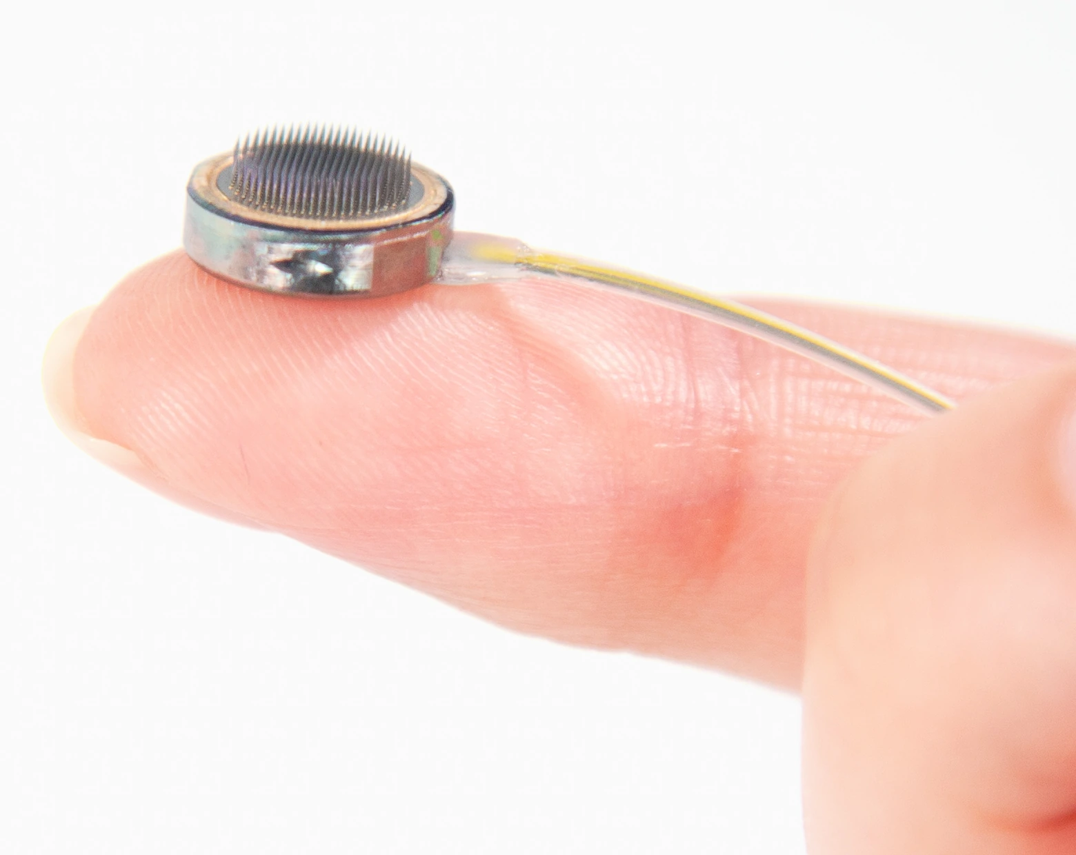
Connexus cortical module on a fingertip, showing its penetrating microelectrodes.
Manufacturer-supplied Connexus cortical-module photograph. No manufacturer endorsement is implied.
Image credit & source
Paradromics, Inc. — official press kit · Paradromics · official press kit · Official press kit — editorial use with credit.
Editorial crop centered on the cortical module; resized and re-encoded. No hardware retouching.
- Code
- C3R
- Reviewed
- 2026-10-07
- Interface
- intracortical
- Evidence stage
- human
Independent, source-linked catalog sheet. Not a manufacturer-issued datasheet, regulatory decision or instructions for clinical use. Human evidence does not establish approval. Source-specific restrictions, conflicts and missing specifications are retained below.
Paradromics Connexus cortical module
Connexus combines a penetrating microwire array with implanted electronics, a flexible lead and a chest transceiver. Its intended applications include speech and computer control for people with severe motor impairment. It remains an investigational device. [1]
Geometry and evidence
| Parameter | Public description | Treatment in the 3D model |
|---|---|---|
| Electrode count | 421 per module [1] | 421 physical microwires |
| Electrode spacing | 300 µm [2] | 300 µm square lattice |
| Insertion depth | 1.5 mm [1, 2] | All tips at Z = 1.5 mm |
| Circular package | Approximately 1 cm diameter [3] | Nominal 10 mm envelope |
| Wire diameter | Older technical slides report <40 µm PtIr wires [4] | 40 µm visualization bound; current exact diameter unknown |
| Exact contact map | No coordinate map | Circularly cropped lattice is reconstructed |
| Housing thickness / tip exposure | Explicit illustrative dimensions; exposed area stays unknown |
The manufacturer’s 2024 photograph shows the circular module used as this model’s visual reference. The 2023 technical slides show a different square package with a 9 mm dimension. That older package dimension is not applied to this model. Photographs guide appearance; they do not supply measured dimensions.
What the model represents
The interactive model includes the module envelope, ceramic face and 421 penetrating wires. Gold marks illustrative tip regions. The Microwire detail button zooms the camera without changing the geometry.
The circular array boundary, 1.5 mm housing thickness, face construction and tip shape are approximations. The deterministic lattice is a simulation reference, not a manufacturer fabrication drawing. Lead routing and ASIC internals are omitted.
Geometry JSON uses millimeters, with the origin at the center of the tissue-facing substrate surface and insertion along +Z. Each site identifies a wire apex; exposed-contact centroids, areas and acquisition channel assignments remain unknown. GLB exports use meters. An electrical model and tissue-coordinate transform are still required for recording or stimulation simulation.
Electrodes and system architecture
Paradromics describes platinum–iridium electrodes and metal/ceramic construction. [3, 4] The current system is fully internalized: a flexible lead connects the cortical interface to an implanted chest transceiver; data crosses the skin optically and power is supplied inductively. [1]
Physical electrode count should not be confused with an analysis channel count. The SfN report analyzes 420 electrodes, while the product page specifies 421 physical microelectrodes. The model does not infer which site is a reference or assign channels. [1, 2]
Human evidence and status
The temporary intraoperative recording announced in June 2025 established an acute human milestone. [5] It is no longer the only announced human implantation: on June 17, 2026, Paradromics announced the first implantation in the Connect-One Early Feasibility Study at the University of Michigan, following the November 2025 IDE authorization. [6]
Study authorization is distinct from commercial approval. The geometry model does not establish long-term safety, recording yield or durability, and company design goals should not be read as demonstrated lifetime performance.
Identity
| Field | Value and source scope |
|---|---|
| Device | Connexus cortical module and fully internalized system |
| Manufacturer | Paradromics |
| Interface class | Intracortical, penetrating microwire array |
| Origin | Paradromics; Connect-One study with the University of Michigan [6] |
| First demonstrated | Temporary intraoperative human recording announced June 2, 2025 [5] |
| First human implant | Acute recording June 2025 [5]; first Connect-One chronic implant announced June 17, 2026 [6] |
| Species studied | Human (investigational); preclinical animal work referenced by the manufacturer but not detailed |
| Regulatory status | Investigational: IDE authorized November 2025; Connect-One Early Feasibility Study. Not commercial approval [6] |
| Function | Recording for intended speech and computer-control applications [1] |
| Target tissue | Cortex; severe motor impairment population intended [1] |
Geometry and architecture
| Field | Value and source scope |
|---|---|
| Interface type | Penetrating microwire array |
| Array layout | Circular module with penetrating wires on a 300 µm square lattice [2]; no coordinate map, so the model lattice is reconstructed |
| Electrode count | 421 physical microwires per module [1]; 420 analyzed in the SfN report [2] |
| Pitch | 300 µm square lattice [2] |
| Electrode lengths | 1.5 mm insertion depth [1, 2]; wire lengths beyond that not reported |
| Shank width and thickness | Older technical slides report wires under 40 µm diameter [4]; current exact diameter not reported. Module about 1 cm circular [3]; the 2023 slides show an older, different square package of 9 mm [4] |
| Tip and exposed site geometry | Exposed area stays unknown |
| Contact coating | Platinum-iridium electrodes [3, 4]; any additional coating not reported |
| Insulation | |
| Insertion method | |
| Anchoring and fixation | Module on cortex with a flexible lead to the chest transceiver [1]; fixation detail not reported |
Electrode and channel physics
| Field | Value and source scope |
|---|---|
| Exposed site area | |
| Electrode material | Platinum-iridium [3, 4] |
| Impedance (with measurement frequency) | |
| Noise floor or SNR | |
| Recording modality | Intracortical neural signals; specific bands not specified |
| Sampling rate | |
| Stimulation capability | |
| Charge injection limit | |
| Reference and ground |
Tissue interface and bioresponse
| Field | Value and source scope |
|---|---|
| Target tissue | Cerebral cortex, penetrating microwires, 1.5 mm insertion depth [1, 2] |
| Insertion trauma and BBB disruption | Inherent to penetrating wires; quantitative data not reported |
| Vascular disruption risk | Placement-dependent; not quantified |
| Micromotion sensitivity | Rigid microwires in soft tissue; comparative data not reported |
| Gliosis and encapsulation | Chronic histology not reported |
| Neuron loss near sites | |
| Foreign-body response mitigation | |
| Typical failure modes | Chronic stability and yield limits typical of intracortical interfaces; no device-specific failure data published |
System architecture
| Field | Value and source scope |
|---|---|
| Onboard electronics | Implanted electronics in the module; internal ASIC detail not reported |
| Data path | Flexible lead to an implanted chest transceiver; optical through-skin data link [1] |
| Telemetry bandwidth | |
| Sampling rate | |
| Power | Inductive power to the implanted transceiver [1] |
| Thermal management | |
| Packaging and hermeticity | Fully internalized system [1]; packaging-stack detail not reported |
| MRI compatibility | |
| Surgical complexity | Open cranial surgery for module placement plus chest transceiver implantation; procedural detail limited |
| Output connectors | Flexible lead from module to chest transceiver [1]; connector detail not reported |
Performance envelope
| Field | Value and source scope |
|---|---|
| Acute yield | Human neural signals recorded intraoperatively, June 2025 [5]; quantitative yield not reported |
| Chronic yield | |
| Stability over time | |
| Longevity | Company design goals exist; demonstrated lifetime not reported |
| Revision and explant experience | Acute intact explant demonstrated, removed in under 20 minutes per the announcement [5]; chronic revision experience not reported |
| Adverse events | Acute procedure reported as successful [5]; no chronic safety dataset public |
| Notable demonstrations | First temporary human recording June 2025 [5]; first Connect-One chronic implant June 2026 [6] |
Clinical and preclinical evidence
| Field | Value and source scope |
|---|---|
| Human subjects | At least one acute recording participant [5] and the first Connect-One implant recipient [6]; full enrollment not pinned here |
| Preclinical cohort | Preclinical cohort details not reported |
| Follow-up duration | Acute (minutes) for the 2025 test; chronic follow-up beginning with the 2026 EFS implant [5, 6] |
| Indications | Severe motor impairment; speech restoration intended [1, 6] |
| Trials and registries | Connect-One Early Feasibility Study; registry identifier not pinned in this sheet |
| Primary outcomes | Acute: surgical feasibility, signal recording, intact explant [5]; chronic outcomes pending |
| Key limitations | Acute-first public evidence; chronic performance and safety require peer-reviewed reporting |
Engineering tradeoffs
| Field | Value and source scope |
|---|---|
| Strengths | High per-module electrode count, demonstrated rapid intraoperative implant and explant, fully internalized chronic system architecture |
| Limitations | Acute-first public evidence, sparse primary technical disclosure, unproven chronic yield and durability |
| Scaling constraints | Surgical workflow, packaging and feedthrough reliability, bandwidth, power and chronic interface biology |
References
- Paradromics — Connexus product and system description.
- Paradromics — SfN 2025, Part 2; published January 21, 2026.
- Paradromics — Neurotech That Lasts; May 14, 2024. Includes the circular module photograph.
- Paradromics technical presentation at BIS, 2023; slide 71. Historical package revision.
- Paradromics — first temporary human recording; June 2, 2025.
- Paradromics and University of Michigan — first Connect-One implantation; June 17, 2026.
Models and reference visualizations
Paradromics Connexus · 421-site reference
Electrode-bearing structure · dimensions in millimeters
Loading 3D viewer…
Model fidelity. Circular module reference guided by the 2024 manufacturer photograph. Count, pitch and depth follow public descriptions; the 421-point circularly cropped square lattice is a reconstruction, not a released contact map. A 10 mm envelope represents “about a centimeter”; housing thickness, face diameter and 80 µm tip regions are illustrative. A dark tissue-facing surface, warm sealing rim and silver housing follow the source photograph; those optical finishes do not establish material composition or extra measured layers. The 40 µm shafts use an upper-bound reference from older technical slides (<40 µm), not a measured current diameter. Those 2023 slides show a different, square package; its 9 mm dimension is not applied to this circular model. Exposed tip area, channel mapping, lead and internal electronics are not modeled.
Color, transparency and surface finish approximate the references. Use Highlight contacts to inspect electrode locations.
Sources & reference images
Dimensions come from the linked specifications; images guide shape only. Reference images remain on their owners’ websites.
- Paradromics — Connexus: 421 electrodes and 1.5 mm depth →
- Paradromics (2026) — 300 µm electrode spacing →
- Paradromics (2024) — circular, approximately 1 cm cortical module →
- Paradromics technical slides (2023), slide 71 — older package and <40 µm PtIr wires →
- Paradromics — circular cortical module photograph (2024) →
JSON includes physical site coordinates, unknown channel mappings and approximation notes. GLB uses meters. These models do not predict recording or stimulation performance.