LIFE (Longitudinal Intrafascicular Electrode)
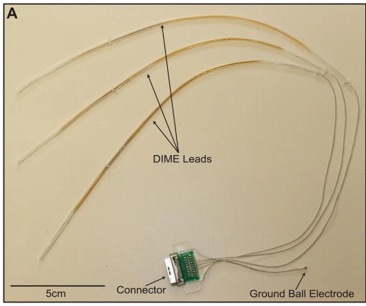
LIFE family example: Thota multi-LIFE DIME assembly with three leads, connector and ball ground. 5 cm source scale retained.
2015 DIME multi-LIFE academic prototype. This is a named LIFE configuration, not the earlier Dhillon human assembly or tfLIFE.
Scale: 5 cm scale bar retained.
Assembly view of multiple bundled LIFEs; individual active-wire segments need the separate deployment close-up and paper dimensions.
Image credit & source
Thota et al., Journal of Neuroscience Methods (2015), Fig. 3A; © 2014 Elsevier B.V. · Thota 2015 · Fig. 3A · Copyright © 2014 Elsevier B.V.; reserved-rights reference.
Photographic panel mechanically cropped from the source; resized and encoded as WebP. Source annotations and scale bars retained; no generative changes.
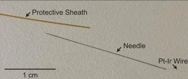
Individual LIFE deployment components: protective sheath, needle and Pt-Ir wire. 1 cm source scale retained.
2015 DIME multi-LIFE academic prototype. This is a named LIFE configuration, not the earlier Dhillon human assembly or tfLIFE.
Scale: 1 cm scale retained.
Wire and delivery needle; the delivery needle is removed after placement. The 25 µm Pt-Ir core and approximately 1 mm active segment are reported specifications, not resolved measurements here.
Image credit & source
Thota et al. (2015), Fig. 2, step 3 · Thota 2015 · Fig. 2 step 3 · Copyright © 2014 Elsevier B.V.; reserved-rights reference.
Photographic panel mechanically cropped from the source; resized and encoded as WebP. Source annotations and scale bars retained; no generative changes.
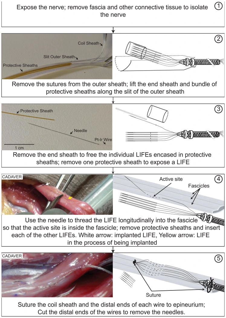
Source deployment figure: LIFE inserted longitudinally into a cadaver nerve fascicle, followed by fixation and removal of delivery needles.
2015 DIME multi-LIFE academic prototype. This is a named LIFE configuration, not the earlier Dhillon human assembly or tfLIFE.
Scale: 1 cm scale applies to the isolated-wire panel only.
Mixed photographs and schematic diagrams; the source states diagrams are not to scale.
Image credit & source
Thota et al. (2015), Fig. 2 · Thota 2015 · Fig. 2 · Copyright © 2014 Elsevier B.V.; reserved-rights reference.
Complete source figure retained; resized and encoded as WebP. No generative changes.
- Code
- ?3?
- Reviewed
- 2026-02-06
- Interface
- pni
- Evidence stage
- human
Independent, source-linked catalog sheet. Not a manufacturer-issued datasheet, regulatory decision or instructions for clinical use. Human evidence does not establish approval. Source-specific restrictions, conflicts and missing specifications are retained below.
LIFE (Longitudinal Intrafascicular Electrode)
All rows follow the shared implant-device template. Measurements belong to the named study or configuration. A blank cell means the reviewed sources do not establish a value. Proposed use, terminal assays and continuously functioning implants are not treated as equivalent.
Identity
| Field | Value and source scope |
|---|---|
| Device | LIFE fine-wire family; 2015 DIME lead is a named multi-LIFE configuration |
| Manufacturer | Academic research fabrication, Thota 2015; not one vendor SKU |
| Interface class | Longitudinal intrafascicular peripheral nerve electrode |
| Origin | Fine-wire LIFE literature; DIME system developed by Thota and collaborators |
| First demonstrated | Earlier LIFE reports cited in Thota 2015; earliest demonstration not independently established in this audit |
| First human implant | Human functional study published by Dhillon and Horch in 2005; not a first implantation date |
| Species studied | Human amputees in Dhillon 2005; cadaver arm and acute rodents in Thota 2015 |
| Regulatory status | Research; authorization for general clinical use not reported |
| Function | Peripheral neural recording and stimulation |
| Target tissue | Axon groups inside peripheral nerve fascicles |
Geometry and architecture
| Field | Value and source scope |
|---|---|
| Interface type | Longitudinal fine-wire intrafascicular interface |
| Array layout | Individual LIFE active segments distributed among fascicles; Thota DIME bundles six wires per lead |
| Electrode count | One active segment per LIFE; 2015 prototype has three six-wire DIME leads plus separate ground. Recording configuration can use five LIFEs and one extrafascicular reference per lead |
| Pitch | Configuration dependent; individually deployed wires have no fixed array pitch |
| Electrode lengths | Approximately 1 mm de-insulated active segment, Thota 2015 |
| Shank width and thickness | 2015 DIME: 25 µm Pt/Ir core, 6 µm PTFE coating, 37 µm insulated diameter. Same paper describes earlier LIFE literature as 27.5 µm wire; not identical configurations |
| Tip and exposed site geometry | Approximately 1 mm exposed wire segment, not a point tip; exact exposure perimeter not reported |
| Contact coating | Pt/Ir wire; no added surface film established in audited Methods |
| Insulation | PTFE-coated wire, silicone bundled lead; protective polyimide deployment sheaths, Thota 2015 |
| Insertion method | Tungsten needle attached to distal wire used to thread longitudinally into fascicle, Thota 2015 |
| Anchoring and fixation | Deployment and anchoring depend on wire routing; DIME coiled wires and silicone sheath provide strain relief |
Electrode and channel physics
| Field | Value and source scope |
|---|---|
| Exposed site area | Not given as measured area; 25 µm core and approximately 1 mm exposure specified for DIME, not converted to an exact exposed area |
| Electrode material | Pt/Ir wire in Thota 2015 |
| Impedance (with measurement frequency) | |
| Noise floor or SNR | |
| Recording modality | Peripheral neural activity from axon groups; acute afferent recording in 2015 and motor intent control in 2005 human study |
| Sampling rate | Configuration dependent; external recording system, exact rate not reported in audited Methods |
| Stimulation capability | Selective sensory and motor stimulation in published use; 2015 acute rodent ankle movements and 2005 human feedback |
| Charge injection limit | |
| Reference and ground | 2015 recording: one wire extrafascicular within nerve as differential reference; separate ball ground in prototype assembly |
Tissue interface and bioresponse
| Field | Value and source scope |
|---|---|
| Target tissue | Within peripheral nerve fascicles |
| Insertion trauma and BBB disruption | BBB: not applicable; needle insertion breaches peripheral fascicle, quantitative injury not reported in reviewed system paper |
| Vascular disruption risk | |
| Micromotion sensitivity | Fine wires risk entanglement and breakage under mechanical stress; coiled DIME bundle and sheaths are intended to reduce that risk, 2015 |
| Gliosis and encapsulation | Peripheral interface, not CNS gliosis; chronic tissue-response rate not reported in audited sources |
| Neuron loss near sites | |
| Foreign-body response mitigation | Small wire diameter and flexible routing are design choices; chronic effectiveness not quantified here |
| Typical failure modes | Wire entanglement and stress-related breakage identified as design risks, Thota 2015; not measured cohort failure rates |
System architecture
| Field | Value and source scope |
|---|---|
| Onboard electronics | None in LIFE; external recording/stimulation in reviewed prototype |
| Data path | 2015 percutaneous DIME leads to external connector and electronics; fully implanted electronics stated as long-term objective, not achieved in that prototype |
| Telemetry bandwidth | Not applicable to wired LIFE prototype |
| Sampling rate | Configuration dependent, external acquisition |
| Power | External electronics for audited prototype |
| Thermal management | |
| Packaging and hermeticity | 2015: silicone-protected bundle and epoxy-insulated connector; percutaneous system, no hermetic lifetime qualification |
| MRI compatibility | |
| Surgical complexity | Nerve/fascicle exposure, multiple needle insertions and lead routing; tested in human cadaver arm, 2015 |
| Output connectors | 2015 custom PCB with Hirose LX multi-channel connector; silicone assembly approximately 6 mm high |
Performance envelope
| Field | Value and source scope |
|---|---|
| Acute yield | Cadaver prototype routed without visually observed mechanical damage; acute rodent functional stimulation/recording, 2015. Not a numerical electrical yield |
| Chronic yield | |
| Stability over time | Chronic stability not established by the 2015 cadaver and acute rodent system study |
| Longevity | Proposed weeks-to-months studies are not observed device lifetime |
| Revision and explant experience | |
| Adverse events | Clinical adverse-event rate not reported in audited sources; cadaver routing is not a safety trial |
| Notable demonstrations | Dhillon 2005 amputees judged and set prosthetic grip force/joint position without visual input; 2015 demonstrates multi-fascicle deployment |
Clinical and preclinical evidence
| Field | Value and source scope |
|---|---|
| Human subjects | Amputees in Dhillon 2005; exact audited participant count not pinned here. 2015 prototype study includes human cadaver, not a living clinical cohort |
| Preclinical cohort | Acute rodents in Thota 2015; cohort count not reported in audited text |
| Follow-up duration | Cadaver/acute deployment in 2015; generic chronic duration not asserted |
| Indications | Experimental prosthetic sensory feedback and motor control |
| Trials and registries | |
| Primary outcomes | Feasibility of direct neural feedback/control and multi-LIFE surgical management |
| Key limitations | LIFE family differs from DIME packaging; acute/cadaver deployment does not establish chronic clinical durability |
Engineering tradeoffs
| Field | Value and source scope |
|---|---|
| Strengths | Fine-wire access to distinct axon populations and human bidirectional functional demonstration |
| Limitations | Fascicle penetration, fragile wires, deployment and lead routing burden |
| Scaling constraints | DIME groups wires to manage multiple insertion sites; each LIFE still requires individual placement |
References
- Thota et al. 2015. A system and method to interface with multiple groups of axons in several fascicles of peripheral nerves. Full DIME Methods; distinguishes earlier LIFE wire geometry.
- Dhillon and Horch 2005. Direct neural sensory feedback and control of a prosthetic arm. Human functional report. Institutional copy.
Models and reference visualizations
LIFE · 2015 DIME single-wire contact window
Single wire and exposure; local crop · dimensions in millimeters
Loading 3D viewer…
Documented measurements
- 25 µm Pt/Ir core and 6 µm radial PTFE: 37 µm insulated diameter
- Approximately 1 mm active segment within a continuing wire
Reconstructed or assumed
- Straight 2 mm display crop
- Half-millimeter insulated stubs on both sides
Not modeled
- Exact stripped perimeter and exposed area
- Remaining wire, needle, bundle, coils and sheaths
Model fidelity. One straight local wire crop from the 2015 DIME fabrication method, not six wires arranged at invented pitch. A 25 µm Pt/Ir core plus 6 µm radial PTFE gives 37 µm insulated diameter. Approximately 1 mm is de-insulated; the paper places this segment about 2 cm from the distal end, so it is not a tip pad. The model retains a 0.5 mm insulated crop stub on each side. The 2 mm crop length and straight pose are display choices, not a full implanted-wire length or deployment trajectory. Exact stripped perimeter and taper are unresolved, so exposed area remains null. The jacket is rendered as ivory PTFE and the exposed core as silver Pt/Ir; this shading is illustrative, not a measured optical response. Distal wire, introducer, strain-relief coils, sheath and other LIFE sites are omitted. No neural recording or stimulation physics is supplied.
Color, transparency and surface finish approximate the references. Use Highlight contacts to inspect electrode locations.
Sources & reference images
Dimensions come from the linked specifications; images guide shape only. Reference images remain on their owners’ websites.
JSON includes physical site coordinates, unknown channel mappings and approximation notes. GLB uses meters. These models do not predict recording or stimulation performance.