Stentrode (Synchron)
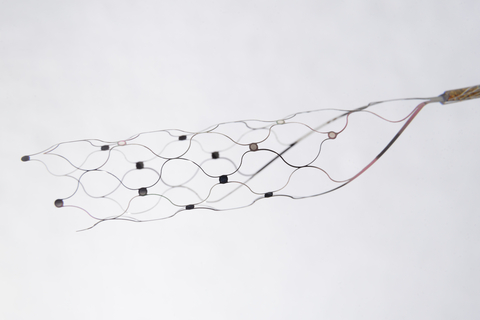
Stentrode scaffold and electrode contacts, with the recording lead extending to the right.
Reference photograph supplied for this gallery; exact hardware revision unspecified.
Image credit & source
Synchron Stentrode reference image supplied by the site owner; original photographer unspecified · Synchron · device background · User-supplied image; source copyright retained.
Supplied image copied intact, byte for byte. All labels, panels, scale bars and embedded metadata retained.
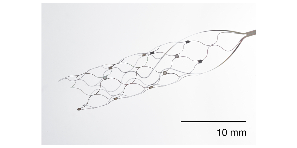
A closer look at the scaffold, electrode contacts, and their connecting wires. Original 10 mm scale retained.
Reference photograph supplied for this gallery; exact hardware revision unspecified.
Image credit & source
Stentrode reference image supplied by the site owner; original photographer unspecified · Synchron · device background · User-supplied image; source copyright retained.
Supplied image copied intact, byte for byte. All labels, panels, scale bars and embedded metadata retained.
- Code
- C3R
- Reviewed
- 2026-10-05
- Interface
- endovascular
- Evidence stage
- human
Independent, source-linked catalog sheet. Not a manufacturer-issued datasheet, regulatory decision or instructions for clinical use. Human evidence does not establish approval. Source-specific restrictions, conflicts and missing specifications are retained below.
Stentrode (Synchron)
The tables use the same field framework as the other implant-device sheets. Values belong to the named study or configuration. A blank cell means the reviewed sources do not establish a value, not that the device lacks that property.
Identity
| Field | Value and source scope |
|---|---|
| Device | Stentrode stent-electrode array |
| Manufacturer | Synchron, Kacker 2025 |
| Interface class | Endovascular cortical recording interface |
| Origin | SWITCH study at Royal Melbourne Hospital, Australia; not a claim about invention priority |
| First demonstrated | |
| First human implant | SWITCH study began May 2019; exact first implantation date is not pinned here |
| Species studied | Human in SWITCH 2023 and Kacker 2025; this audit does not enumerate earlier animal cohorts |
| Regulatory status | Investigational feasibility study; commercial authorization not established by these papers |
| Function | Motor-intent recording for computer control |
| Target tissue | Superior sagittal sinus adjacent to motor cortex |
Geometry and architecture
| Field | Value and source scope |
|---|---|
| Interface type | Endovascular, without cortical penetration |
| Array layout | Contacts on a self-expanding nitinol scaffold; Kacker 2025 nominal scaffold 8 x 40 mm. Exact contact map is not reported |
| Electrode count | 16 physical contacts, Kacker 2025; 12 and 8 retained for analysis in its two participants |
| Pitch | Approximately 3 mm interelectrode spacing; not a complete 3D map, Kacker 2025 |
| Electrode lengths | Not applicable to cortical shanks; scaffold length 40 mm in Kacker 2025 |
| Shank width and thickness | Not applicable; strut dimensions not reported |
| Tip and exposed site geometry | 500 µm contact diameter, Kacker 2025. Schone 2025 preprint separately reports 300 µm; configurations are not equated |
| Contact coating | Platinum contacts, Kacker 2025 |
| Insulation | |
| Insertion method | Jugular-vein catheter delivery into superior sagittal sinus, Kacker 2025 |
| Anchoring and fixation | Expanded scaffold apposed to sinus wall, verified by angiography in Kacker 2025 |
Electrode and channel physics
| Field | Value and source scope |
|---|---|
| Exposed site area | SWITCH 2023: 0.3 mm². A 500 µm circular face in Kacker 2025 gives about 196,350 µm² geometrically, not an independently measured exposed area; discrepancy retained |
| Electrode material | Platinum contacts on nitinol scaffold, Kacker 2025 |
| Impedance (with measurement frequency) | SWITCH 2023: mean (SD) 37 (11) kΩ, frequency unstated in device description. Kacker 2025: measured at 100 Hz with 10 nA, channel-level values in Tables 1 and 2; not a 1 kHz rating |
| Noise floor or SNR | Kacker 2025 Tables 1 and 2 report per-channel low- and high-gamma task SNR; not one device noise-floor specification |
| Recording modality | Field potentials with gamma/high-gamma motor modulation, Kacker 2025 |
| Sampling rate | 2,000 Hz, Kacker 2025 |
| Stimulation capability | Clinical papers reviewed here concern recording |
| Charge injection limit | |
| Reference and ground | Kacker 2025: one Stentrode channel used as common reference. SWITCH 2023 instead describes a reference on the receiver-transmitter unit; source-specific descriptions retained |
Tissue interface and bioresponse
| Field | Value and source scope |
|---|---|
| Target tissue | Venous wall adjacent to cortex, not intracortical placement |
| Insertion trauma and BBB disruption | No cortical penetration in the described procedure; quantitative BBB injury not reported |
| Vascular disruption risk | SWITCH monitored patency, migration and thrombosis; no occlusion or migration in four implanted participants at 12 months. Not a general risk estimate |
| Micromotion sensitivity | |
| Gliosis and encapsulation | Cortical gliosis measurements not reported in these human studies |
| Neuron loss near sites | |
| Foreign-body response mitigation | |
| Typical failure modes | No device-related serious failure in the four-person 12-month SWITCH cohort; longer-term failure rates not reported |
System architecture
| Field | Value and source scope |
|---|---|
| Onboard electronics | Lead-connected implantable receiver-transmitter in infraclavicular subcutaneous pocket, SWITCH 2023 |
| Data path | Stent contacts to implanted receiver-transmitter to external telemetry unit to computer, Kacker 2025 |
| Telemetry bandwidth | |
| Sampling rate | 2,000 Hz, Kacker 2025 |
| Power | |
| Thermal management | |
| Packaging and hermeticity | Fully implanted sensing device, lead and receiver-transmitter; hermetic qualification not reported |
| MRI compatibility | |
| Surgical complexity | Neurointerventional transvenous delivery and chest pocket; no cortical craniotomy in described procedure |
| Output connectors | Internal lead plus wireless external receiver; connector specification not reported |
Performance envelope
| Field | Value and source scope |
|---|---|
| Acute yield | |
| Chronic yield | |
| Stability over time | SWITCH: mean signal bandwidth 233 (16) Hz stable across 12 months in four participants |
| Longevity | 12-month SWITCH follow-up; not a maximum lifetime |
| Revision and explant experience | |
| Adverse events | SWITCH: no serious adverse events, vessel occlusion or migration in four implanted participants; eight mild device effects resolved without intervention |
| Notable demonstrations | All four SWITCH participants controlled a computer; Kacker 2025 maps motor modulation in two people with ALS |
Clinical and preclinical evidence
| Field | Value and source scope |
|---|---|
| Human subjects | SWITCH: five enrolled, four implanted and analyzed; Kacker 2025: two participants. Do not sum as unique people |
| Preclinical cohort | |
| Follow-up duration | |
| Indications | Severe upper-limb paralysis; ALS or primary lateral sclerosis in SWITCH |
| Trials and registries | SWITCH prospective first-in-human study; registry ID not reported in this audit |
| Primary outcomes | Safety, venous patency and computer-control feasibility |
| Key limitations | Small selected cohorts, variable decoding strategies, limited follow-up, source-specific geometry and reference descriptions |
Engineering tradeoffs
| Field | Value and source scope |
|---|---|
| Strengths | Computer control demonstrated without penetrating cortex; fully implanted system in reviewed cohorts |
| Limitations | Population field potentials rather than single-unit recording; evidence limited to small cohorts |
| Scaling constraints | Contact placement must fit venous anatomy; no quantitative scaling ceiling established |
3D reference, revision 2
The revised model uses curved flat struts and annular electrode mounts guided by Synchron’s close-up photograph, with a schematic proximal lead segment. Contact detail shows the mounted disk at physical scale. The selected published configuration remains 16 contacts, 500 µm diameter and a nominal 8 × 40 mm scaffold.
Strut cross section (80 × 40 µm), mount diameter (680 µm), contact thickness (50 µm), lattice topology and the 12 mm × 0.5 mm lead stub are illustrative. The lead is a short visual envelope, not the actual implanted cable length or conductor routing. The staggered contact strip is reconstructed; it does not replace a manufacturer channel map. The model represents a nominal expanded scaffold, not vessel deformation or a delivery state.
JSON preserves revision metadata, approximation notes and outward-facing site normals. GLB exports the complete assembly in meters. The exact clinical revision and its validated electrical parameters must be established before using this geometry in a physiological simulation.
References
-
Yoo PE, et al. “Motor neuroprosthesis implanted with neurointerventional surgery improves capacity for activities of daily living tasks in severe paralysis: first in-human experience.” J NeuroInterv Surg (Epub 2020 Oct 28; 2021 Feb). DOI: 10.1136/neurintsurg-2020-016862. PubMed: https://pubmed.ncbi.nlm.nih.gov/33115813/
-
Mitchell P, et al. “Assessment of Safety of a Fully Implanted Endovascular Brain-Computer Interface for Severe Paralysis in 4 Patients: The Stentrode With Thought-Controlled Digital Switch (SWITCH) Study.” JAMA Neurology (2023). PMC full text: https://pmc.ncbi.nlm.nih.gov/articles/PMC9857731/
-
Kacker K, et al. “Motor activity in gamma and high gamma bands recorded with a Stentrode from the human motor cortex in two people with ALS.” J Neural Eng (2025), section 2.2 and Figure 1. https://pmc.ncbi.nlm.nih.gov/articles/PMC11956166/
-
Schone HR, et al. “Motor Cortex Coverage Predicts Signal Strength of a Stentrode Endovascular Brain-Computer Interface.” medRxiv (2025 preprint). https://www.medrxiv.org/content/10.1101/2025.09.19.25335875v1.full
Models and reference visualizations
Synchron Stentrode · 16-contact reference
Electrode-bearing structure · dimensions in millimeters
Loading 3D viewer…
Model fidelity. Named Kacker et al. (2025) reference, with 15 recording signals and one reference electrode; channel assignments remain unknown. The sparse, elongated lattice and convergent proximal neck follow Figure 1a and the manufacturer close-up. Ten axial intervals, eight circumferential nodes, the 4 mm neck, 80 × 40 µm strut section, 680 µm mounts with 60 µm support thickness, 50 µm contact thickness and the 12 mm × 0.5 mm lead stub are visual reconstructions. Sixteen contacts sit on supported lattice nodes in eight circumferentially distributed pairs. Each pair has approximately 3.12 mm center spacing; successive axial levels are 4 mm apart. This is a photo-informed arrangement, not a recovered contact map or a claim that every spacing equals the published approximately 3 mm. Nominal diameter is not a vessel-constrained deployment. The derived 0.196 mm² face area differs from SWITCH’s separately reported 0.3 mm² and a later preprint’s 300 µm disks. Internal wiring, delivery system and chest telemetry are omitted. Platinum electrode faces and metallic scaffold finishes follow the material descriptions; colors and optical properties are illustrative.
Color, transparency and surface finish approximate the references. Use Highlight contacts to inspect electrode locations.
Sources & reference images
Dimensions come from the linked specifications; images guide shape only. Reference images remain on their owners’ websites.
- Kacker et al. (2025) — device dimensions, section 2.2 and Figure 1 →
- University of Melbourne — full paper PDF →
- SWITCH study (2023) — separately reported contact area →
- Schone et al. (2025 preprint) — separately reported 300 µm contacts →
- Synchron — electrode close-up and research library →
- Synchron — contact mount and curved strut photograph →
JSON includes physical site coordinates, unknown channel mappings and approximation notes. GLB uses meters. These models do not predict recording or stimulation performance.